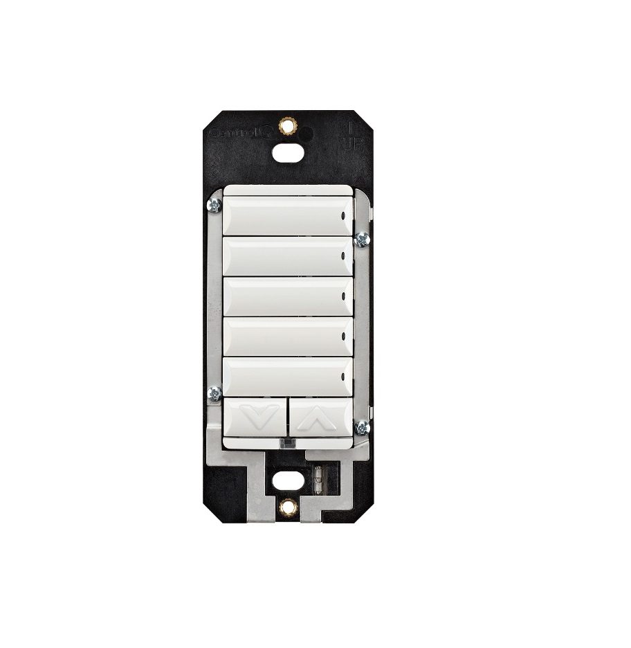
Control4 C4-KC120277 Wireless Configurable Keypad
Supported model
- C4-KC120277 Wireless Configurable Keypad
Introduction
The Control4® Configurable Keypad is intended for use in a Control4 system. It installs in a standard wall box using typical wiring standards and communicates to the Control4 system using a wireless connection.
Box contents
- Configurable Keypad
- Keycap Button Kit
- Wire nuts · Warranty card
- Configurable Keypad Installation Guide (this document)
- Keypad Button Installation Guide
Specifications
The specifications are described below.
| Model number | C4-KC120277-xx |
| Power requirements | 120-277V AC +/-10% 50/60 Hz 36-48V DCThis device requires a neutral AC connection. |
| Power consumption | 120V: 350mW277V: 540mW36V DC: 430mW |
|
Environmental |
|
| Operational temperature | 0 to 40 ˚C (32 to 104 ˚F) |
| Humidity | 5% to 95% non-condensing |
| Storage | -20 to 70 ˚C (-4 to 158 ˚F) |
|
Miscellaneous |
|
| Control communications | Zigbee, IEEE 802.15.4, 2.4 GHz, 15-channel spread spectrum radio |
| Wallbox volume | 4.75 cubic inches |
| Weight | 0.05 kg (0.12 lb.) |
| Shipping weight | 0.08 kg (0.18 lb.) |
Warnings And Considerations
![]() WARNING! Turn OFF electrical power before installing or servicing this product. Improper use or installation can cause SERIOUS INJURY, DEATH or LOSS/DAMAGE OF PROPERTY.
WARNING! Turn OFF electrical power before installing or servicing this product. Improper use or installation can cause SERIOUS INJURY, DEATH or LOSS/DAMAGE OF PROPERTY.![]() WARNING! This device must be protected by a circuit breaker (20A max).
WARNING! This device must be protected by a circuit breaker (20A max).![]() WARNING! Ground this device in accordance with the National Electric Code (NEC) requirements. DO NOT rely solely upon the yoke plate’s contact with a metal wallbox for adequate grounding. Use the device’s ground wire to make a secure connection to the safety ground of the electrical system.
WARNING! Ground this device in accordance with the National Electric Code (NEC) requirements. DO NOT rely solely upon the yoke plate’s contact with a metal wallbox for adequate grounding. Use the device’s ground wire to make a secure connection to the safety ground of the electrical system.![]() IMPORTANT! This device must be installed by a licensed electrician in accordance with all national and local electrical codes.
IMPORTANT! This device must be installed by a licensed electrician in accordance with all national and local electrical codes.![]() IMPORTANT! If you are unsure about any part of these instructions, consult a qualified electrician.
IMPORTANT! If you are unsure about any part of these instructions, consult a qualified electrician.![]() IMPORTANT! Use this device only with copper or copper-clad wire. Do not use aluminum wiring. This product has not been approved for use with aluminum wiring.
IMPORTANT! Use this device only with copper or copper-clad wire. Do not use aluminum wiring. This product has not been approved for use with aluminum wiring.![]() IMPORTANT! Using this product in a manner other than outlined in this document voids your warranty. Further, Control4 is NOT liable for any damage incurred with the misuse of this product. See “Troubleshooting.”
IMPORTANT! Using this product in a manner other than outlined in this document voids your warranty. Further, Control4 is NOT liable for any damage incurred with the misuse of this product. See “Troubleshooting.”![]() IMPORTANT! Do NOT use a power screwdriver to install this device. If you do, you may overtighten the screws and strip them. Also, overtightening the screws may interfere with proper button operation.
IMPORTANT! Do NOT use a power screwdriver to install this device. If you do, you may overtighten the screws and strip them. Also, overtightening the screws may interfere with proper button operation.![]() IMPORTANT! This is an electronic device with intricate components. Handle and install with care!
IMPORTANT! This is an electronic device with intricate components. Handle and install with care!![]() IMPORTANT! When used in conjunction with an Auxiliary Keypad (C4-KA-xx), the wire connecting the Auxiliary Keypad to the Configurable Keypad must not exceed 45 m (150 ft.) at 120V AC, and 30 m (100 ft.) at 277V AC.
IMPORTANT! When used in conjunction with an Auxiliary Keypad (C4-KA-xx), the wire connecting the Auxiliary Keypad to the Configurable Keypad must not exceed 45 m (150 ft.) at 120V AC, and 30 m (100 ft.) at 277V AC.
Installation Instructions
- Ensure that the location and intended use meet the following criteria:● When replacing a traditional 3-way switch, refer to the “Two-Location” sample wiring configurations provided in the appropriate load control device installation guide.● Install in accordance with all national and local electrical codes.● The range and performance of the wireless control system is highly dependent on the following: (1) distance between devices; (2) layout of the home; (3) walls separating devices; and (4) electrical equipment located near devices.
- Turn o the local electrical power by either switching o the circuit breaker or removing the fuse from the fuse box. To ensure the wires do NOT have power running to them, use an inductive voltage detector.NOTE: The wallbox wiring shown in this document is an example. Your wire colors and functions may dire. If you are not sure which wires are the Line In/Hot, Neutral, and Earth Ground wires, have a trained electrician do the installation.
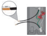
- Prepare each wire. Wire insulation should be stripped back 5/8 of an inch from the wire end (see Figure 1).Figure 1. Strip wire insulation
 IMPORTANT! Not grounding this product, as described in the section, “Warnings and Considerations,” may result in an installation less immune to damage caused by electrical disturbances, such as ESD or lightning, and may void the warranty.
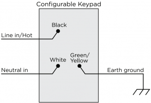
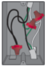
 - Identify and connect the keypad wires to the wallbox wires using the wire nuts as shown in Figure 2 below.Figure 2. Keypad wiring TIP: If you are using a Control4 push-on (screw less) faceplate in a multirange installation, attach the black faceplate sub-plate to all of the devices that will be installed into the wallbox prior to attaching the devices to the wallbox. This will help ensure that all the devices are properly aligned and on the same plane after installation.
- Fit the wires back into the wallbox. Bend the wires in a zigzag pattern so that they easily fold into the wallbox (Figure 3).Figure 3. Bend the wires
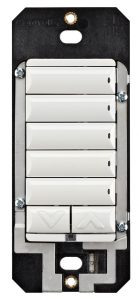
- Align the keypad to the wallbox (the model # label should be at the bottom) and fasten it with screws. Tighten the screws until the back side of the yoke plate is even with the wall surface, but no further. Overtightening can warp the configurable keypad and cause mechanical malfunction.
- Install the Top Actuator Bar, Bottom Sensor Bar, and buttons following the instructions in the “Button Installation” section below.
- Install the Control4 Faceplate following the instructions in the Faceplate Installation Guide or attach a standard Decora-style faceplate.
- Turn on power at the circuit breaker or replace the fuse the fuse box.
For information about how to install or remove the buttons on the configurable keypad, see the Keypad Buttons Installation Guide.
Operation And Configuration
On initial power up, all status LEDs on the keypad will illuminate green indicating that the device has power. Until the keypad has been configured into a Control4 system, it will not control any loads. To set up this keypad for use with a Control4 system, refer to the Composer Pro User Guide.
Button tap sequences
The button tap sequences are defined in the table below. Button tap sequences that require a single (1) button should use the top-most button installed on the keypad. Button tap sequences requiring two (2) buttons should use the top most and bottom-most buttons installed on the keypad.
|
Function |
Button sequence |
| Identify | 4 |
| Zigbee channel | 7 |
| Reboot | 15 |
| Factory reset | 9-4-9 |
| Leave mesh and reset | 13-4-13 |
Troubleshooting
If the LEDs do not light up indicating that the keypad is receiving power::
- Ensure circuit breaker is not turned OFF or tripped.
- Check for proper wiring (see Step 2 in “Installation Instructions”).
Care and cleaning
- Do NOT paint the keypad or its wall plate.
- Do NOT use any chemical cleaners to clean the keypad.
- Clean surface of the keypad with a soft damp cloth as needed.
Warranty and legal notices
Find details of the product’s Limited Warranty at snapav.com/warranty or request a paper copy from Customer Service at 866.424.4489. Find other legal resources, such as regulatory notices and patent information, at snapav.com/legal.
References
[xyz-ips snippet=”download-snippet”]