Control4® Decora Wired Keypad Installation Guide
Supported model
C4-KCB-XX Decora® Wired Keypad
Introduction
The Control4® Decora Wired Keypad is intended for use in a Control4 system. It installs in a standard US wallbox. Communication to the Control4 system is via RS485 protocol and wiring. For RS-485 wiring topologies, refer to the Keypad Bus Wiring Guide (ctrl4.co/buswiring).
Box contents
- Decora® Wired Keypad
- Keycap Button Kit
- Pluggable Terminal Block
- Warranty card
Specifications
| Model number | C4-KCB-XX |
| Power requirements | 48VDC |
| Power consumption | Maximum 48V DC 1.2W
Minimum 48V DC 0.7W |
|
Environmental |
|
| Operational temperature | 0 to 40 ˚C (32 to 104 ˚F) |
| Humidity | 5% to 95% non-condensing |
| Storage | -20 to 70 ˚C (-4 to 158 ˚F) |
|
Miscellaneous |
|
| Control communications | RS-485 |
| Weight | 0.045 kg (0.1 lb.) |
| Shipping weight | 0.14 kg (0.3 lb.) |
Warnings and considerations
![]() Important: Using this product in a manner other than outlined in this document voids your warranty. Further, Control4 is not liable for any damage incurred with the misuse of this product. See “Troubleshooting.”
Important: Using this product in a manner other than outlined in this document voids your warranty. Further, Control4 is not liable for any damage incurred with the misuse of this product. See “Troubleshooting.”
![]() Important: Do not use a power screwdriver to install this device. If you do, you may overtighten the screws and strip them. Also, overtightening the screws may interfere with proper button operation.
Important: Do not use a power screwdriver to install this device. If you do, you may overtighten the screws and strip them. Also, overtightening the screws may interfere with proper button operation.
![]() Important: This is an electronic device with intricate components. Handle and install with care!
Important: This is an electronic device with intricate components. Handle and install with care!
![]() Caution! Do not exceed the number of keypads per power supply as indicated in the Keypad Bus Wiring Guide. Exceeding the maximum number of keypads will result in overheating the wires and/or failed devices.
Caution! Do not exceed the number of keypads per power supply as indicated in the Keypad Bus Wiring Guide. Exceeding the maximum number of keypads will result in overheating the wires and/or failed devices.
Installation instructions
![]() Caution! When wiring the keypad, make sure that either:
Caution! When wiring the keypad, make sure that either:
- The Bus Power Supply is not powered on.– OR –
- The pluggable connector is disconnected from the Bus Power Supply.
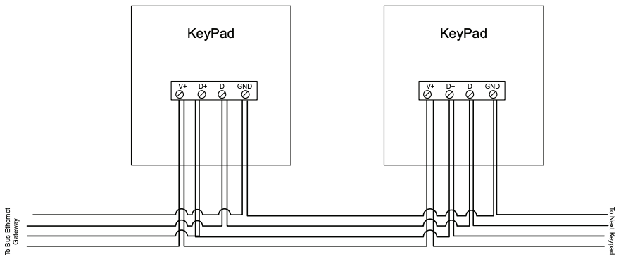
- Prepare the cable for termination by stripping the outer sheath and individual wires, and then wire into the pluggable terminal block.
- Wire the keypads as shown below.Figure 1. Keypad wiring
 Tip: If you are using a Control4 push-on (screwless) faceplate in a multi-gang installation, attach the black faceplate subplate to all of the devices that will be installed into the wallbox before attaching the devices to the wallbox. This will help ensure that all devices are properly aligned and on the same plane after installation.
 - Fit the wires back into the wallbox.
- Align the keypad to the wallbox (the model number label should be at the bottom), then fasten it with the included screws.Important: Tighten the screws until the back side of the yoke plate is even with the wall surface, but no further. Overtightening can warp the keypad and cause it to malfunction.
- Install the top actuator bar, bottom sensor bar, and buttons following the instructions in the Keypad Buttons Installation Guide (ctrl4.co/butn).
- Install the Control4 faceplate following the instructions in the Faceplate Installation Guide or attach a standard Decora-style or square faceplate.
- Ensure that the Bus Power Supply is installed correctly and powered on. For instructions, see the Bus Power Supply, 48V Installation Guide (ctrl4.co/bps48).
More help
For the latest version of this guide and to view additional materials, open the URL below or scan the QR code. Your device must be able to view PDFs.

Wiring diagrams
For bus wiring details, refer to the Keypad Bus Wiring Guide (ctrl4.co/buswiring).
Operation and configuration
On initial power up, all status LEDs on the keypad will illuminate green, indicating that the device has power. Until the keypad has been configured into a Control4 system, it will not control any loads. To set up this keypad for use with a Control4 system, refer to the Composer Pro User Guide (ctrl4.co/cpro-ug).
The button tap sequences are defined in the table below. Button tap sequences that require a single button should use the top-most button installed on the keypad. Button tap sequences requiring two buttons should use the top-most and bottom-most (or bottom-left) buttons installed on the keypad.
|
Function |
Button sequence |
| Identify | 4 |
| Reboot | 15 |
| Factory reset | 9-4-9 |
| Unidentify | 13-4-13 |
Troubleshooting
If the LEDs do not light up indicating that the keypad is receiving power:
- Ensure that the Bus Power Supply is powered on.
- Ensure that the Bus Ethernet Gateway is powered on and connected.
- Check for proper wiring (see “Installation instructions” above).
- For help on the installation or operation of this product, email or call the Control4 Technical Support Center. Provide your exact model number. Contact [email protected] or see www.control4.com.
Care and cleaning
- Do not paint the keypad or its wall plate.
- Do not use any chemical cleaners to clean the keypad.
- Clean surface of the keypad with a soft damp cloth as needed.
Regulatory/safety information
Find details of the product’s Limited Warranty at snapav.com/warrantyor request a paper copy from Customer Service at 866.424.4489.Find other legal resources, such as regulatory notices and patent information, at snapav.com/legal.
References
[xyz-ips snippet=”download-snippet”]