![]()
Keypad DimmerInstallation Guide
Supported models
- C4-KD120 Keypad Dimmer, 120V
- C4-KD277 Keypad Dimmer, 277V
Introduction
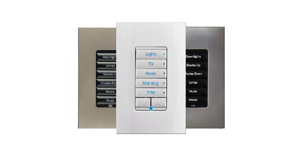
The Control4® Keypad Dimmer operates independently or as part of a Control4 home automation system. It installs in a standard back box using typical wiring standards and communicates to the Control4 system using a wireless connection.
Box contents
- Keypad Dimmer
- Keycap Button Kit
- Wire nuts
- Warranty card
- Keypad Dimmer Installation Guide (this document)
- Keypad Button Installation Guide
Specifications and supported load types
The specifications are described below.
| Model numbers | C4-KD120-xx. C4-KD277-xx | ||
| Power requirements | C4-KD120: 120V AC +/-10%. 50/60 Hz C4-KD277: 277V AC +/-10%. 50/60 HzThis device can function with or without a neutral AC connection depending on load type. Wiring with a neutral is always the preferred wiring method (if possible). See load types and “Sample Wiring Configurations” below.When wired without a neutral, loads may appear dimmer. | ||
| Power consumption | C4-KD12O: 786mW: C4-KD277: 2.51W | ||
| Load types and ratings | |||
| Supported load types | Incandescent, halogen, electronic (solid-state) low voltage (ELV) transformers. magnetic (iron core. inductive) low voltage (MLV) transformers. phase-dimmable fluorescents, compact fluorescents, and LEDs.Important: Do not use with non-dimmable loads. | ||
| C4-KD120 maximum load | 1 Gang | 2 Gang | 3+ Gang |
| Incandescent (tungsten) | 600w | 550w | 500W |
| Halogen | 600W | 550W | 500W |
| Fluorescent” | 300w | 300w | 300W |
| Compact fluorescent (CFL)’ | 300W | 300W | 300W |
| LED’ | 120w | 120W | 120W |
 * NOTES:
- The maximum load requirements for fluorescent, CFL and LED loads can vary greatly depending upon the specific fixture and/or bulb being used. These load types have significant in-rush current which can trip the protection circuitry on the device.
- The quality and performance of these load types vary greatly from manufacturer to manufacturer. When using these load types, we recommend testing in advance. If problems are found, simply changing ta different bulb manufacturers may solve the problem.
- Additionally, we do not recommend the use of fluorescent, CFL, or LED loads without a neutral wire connected to the dimmer due to the capacitive nature of these load types.
- Wiring with a neutral is always the preferred wiring method (if possible).
Warnings and considerations
 WARNING! Turn OFF electrical power before installing or servicing this product. Improper use or installation can cause SERIOUS INJURY, DEATH, or LOSS/DAMAGE OF PROPERTY.WARNING! This device must be protected by a circuit breaker (20A max). WARNING! Ground this device in accordance with the National Electric Code (NEC) requirements. DO NOT rely solely upon the yoke plate’s contact with a metal wall box for adequate grounding. Use the device’s ground wire to make a secure connection to the safety ground of the electrical system.
![]() IMPORTANT! This device must be installed by a licensed electrician in accordance with all national and local electrical codes.
IMPORTANT! This device must be installed by a licensed electrician in accordance with all national and local electrical codes.![]() IMPORTANT! For wiring the dimmer, we recommend always using a neutral wire when possible. See Figure 6.
IMPORTANT! For wiring the dimmer, we recommend always using a neutral wire when possible. See Figure 6.![]() IMPORTANT! If you are unsure about any part of these instructions, consult a qualified electrician.
IMPORTANT! If you are unsure about any part of these instructions, consult a qualified electrician.![]() IMPORTANT! Use this device only with copper or copper-clad wire. Do not use aluminum wiring. This product has not been approved for use with aluminum wiring.
IMPORTANT! Use this device only with copper or copper-clad wire. Do not use aluminum wiring. This product has not been approved for use with aluminum wiring.![]() IMPORTANT! To reduce the risk of overheating and possible damage to other equipment, do not install to control a receptacle or a motor-operated appliance.
IMPORTANT! To reduce the risk of overheating and possible damage to other equipment, do not install to control a receptacle or a motor-operated appliance.![]() IMPORTANT! This product generates heat during normal operation.
IMPORTANT! This product generates heat during normal operation.![]() IMPORTANT! Using this product in a manner other than outlined in this document voids your warranty. Further, Control4 is NOT liable for any damage incurred with the misuse of this product. See “Troubleshooting.”
IMPORTANT! Using this product in a manner other than outlined in this document voids your warranty. Further, Control4 is NOT liable for any damage incurred with the misuse of this product. See “Troubleshooting.”![]() IMPORTANT! Do NOT use a power screwdriver to install this device. If you do, you may overtighten the screws and strip them. Also, overtightening the screws may interfere with proper button operation.
IMPORTANT! Do NOT use a power screwdriver to install this device. If you do, you may overtighten the screws and strip them. Also, overtightening the screws may interfere with proper button operation.![]() IMPORTANT! This is an electronic device with intricate components.Handle and install with care!
IMPORTANT! This is an electronic device with intricate components.Handle and install with care!![]() IMPORTANT! Control4 does not guarantee the performance of any bulb or lamp/fixture in your environment. CUSTOMER ASSUMES ALL RISKS, INCLUDING ANY DAMAGE TO CONTROL4 PRODUCTS, ASSOCIATED WITH (i) THE TYPE, LOAD RATING AND QUALITY OF THE BULB AND LAMP/FIXTURE, OR (ii) ANY USE OR INSTALLATION NOT IN ACCORDANCE WITH THE DOCUMENTATION FURNISHED BY CONTROL4, EITHER WITH THE CONTROL4 PRODUCT OR AT WWW.CONTROL4.COM.
IMPORTANT! Control4 does not guarantee the performance of any bulb or lamp/fixture in your environment. CUSTOMER ASSUMES ALL RISKS, INCLUDING ANY DAMAGE TO CONTROL4 PRODUCTS, ASSOCIATED WITH (i) THE TYPE, LOAD RATING AND QUALITY OF THE BULB AND LAMP/FIXTURE, OR (ii) ANY USE OR INSTALLATION NOT IN ACCORDANCE WITH THE DOCUMENTATION FURNISHED BY CONTROL4, EITHER WITH THE CONTROL4 PRODUCT OR AT WWW.CONTROL4.COM.![]() IMPORTANT! When used in conjunction with an Auxiliary Keypad (C4-KA-xx), the wire connecting the Auxiliary Keypad to the dimmer must not exceed 45 m (150 ft.) at 120V AC and 30 m (100 ft.) at 277V AC.
IMPORTANT! When used in conjunction with an Auxiliary Keypad (C4-KA-xx), the wire connecting the Auxiliary Keypad to the dimmer must not exceed 45 m (150 ft.) at 120V AC and 30 m (100 ft.) at 277V AC.
Installation instructions
- Ensure that the location and intended use meet the following criteria:• Do not exceed the load capacity requirements of the dimmer. In multi-gang installations, a reduction of the dimmers’ capacity is required to allow the dimmers to be installed side-by-side. Refer to the load ratings in the specifications above for details.• Install in accordance with all national and local electrical codes.• The range and performance of the wireless control system is highly dependent on the following: (1) distance between devices; (2) layout of the home; (3) walls separating devices; and (4) electrical equipment located near devices.
- If installing in a multi-gang scenario, use pliers to remove the inner-side breakaway tabs. Bend each tab forward first, and then back and forth until it breaks off. Remove the inner-side tabs ONLY on any device side that will be adjacent to another device. DO NOT remove tabs on any side that will become the outer side of a group of devices. Handle the device with care after removing the tabs, as the broken edge can be sharp.
- Turn off the local electrical power by either switching off the circuit breaker or removing the fuse from the fuse box. To ensure the wires do NOT have power running to them, use an inductive voltage detector.NOTE: The backbox wiring shown in this document is an example. Your wire colors and functions may differ. If you are not sure which wires are the LIne In/Hot, Neutral, Load, Traveler, and Earth Ground wires, have a trained electrician perform the installation.
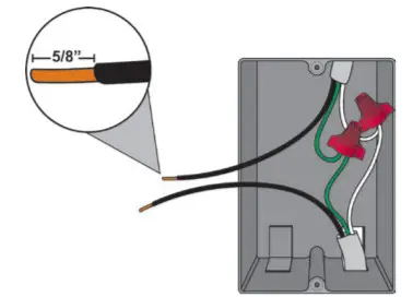
- Prepare each wire. Wire insulation should be stripped back 5/8 of an inch from the wire end (see Figure 1).Figure 1. Strip wire insulation

- Identify your wiring application and then see the appropriate wiring diagram in the “Sample Wiring Configurations” section below. IMPORTANT! Not grounding this product, as described in the “Warnings and Considerations” section, may result in an installation less immune to damage caused by electrical disturbances, such as ESD or lightning, and may void the warranty.
- Identify and connect the dimmer wires to the backbox wires using the wire nuts. IMPORTANT! The yellow wire is not a traditional traveler. It cannot directly power a lighting load. It must be used only to connect to a Control4 Auxiliary Keypad. See “Sample Wiring Configurations.” TIP: If you are using a Control4 push-on (screwless) faceplate in a multi-gang installation, attach the black faceplate subplate to all of the devices that will be installed into the backbox prior to attaching the devices to the backbox. This will help ensure that all the devices are properly aligned and on the same plane after installation.
- Fit the wires back into the backbox. Bend the wires in a zigzag pattern so that they easily fold into the backbox (Figure 2).Figure 2. Bend the wires
- Align the dimmer to the backbox (the load rating label should be at the bottom) and fasten it with screws. Tighten the screws until the backside of the yoke plate is even with the wall surface, but no further. Overtightening can warp the dimmer and cause mechanical malfunction.
- Install the Control4 Faceplate following the instructions in the Faceplate Installation Guide or attach a standard Decora-style faceplate.
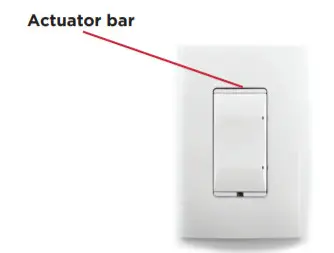
- Attach the buttons, actuator bar, and sensor bar as described in the Keypad Button Installation Guide.
- Turn on power at the circuit breaker or replace the fuse from the fuse box.
 TIP: If you are using a Control4 push-on (screwless) faceplate in a multi-gang installation, attach the black faceplate subplate to all of the devices that will be installed into the backbox prior to attaching the devices to the backbox. This will help ensure that all the devices are properly aligned and on the same plane after installation.
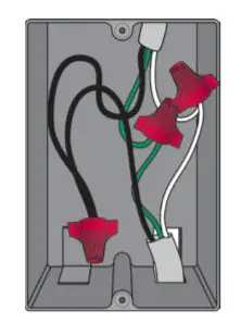
NOTE: If the light flickers, adjust the dimmer’s max/in settings in Composer (for example, min 15%, max 85%). See ctrl4.co/ dimmer settings.
Operation and configuration
On initial power-up, all status LEDs on the dimmer will illuminate green indicating that the device has power. To set up this dimmer for use with a Control4 system, refer to the Composer Pro User Guide.To operate this dimmer as a stand-alone device prior to configuration in Composer Pro:
- If the light is off, click any button to turn the light on.
- If the light is on, click any button to turn the light off.
- Press and hold any button to ramp the light up/down. Release the button at the desired light level.
- If they split up/down buttons have been installed in the bottom button slot, the up and down arrows will ramp and fade the light respectively.
Air gap switchDuring routine lamp replacement, you should remove power from the lamp by engaging the air gap mechanism.
- To engage, press on the right side of the top actuator bar until the left side pops out. All LEDs on the dimmer will turn off and the dimmer will no longer control the light when the air gap mechanism has been engaged.
- To return power to the dimmer and lamp, press on the left side of the top actuator bar until it snaps back into place.Figure 3. Dimmer with actuator bar
Button tap sequencesThe button tap sequences are defined in the table below. Button tap sequences that require a single (1) button should use the top button. Button tap sequences requiring two (2) buttons should use the top-most and bottom-most buttons installed on the Keypad Dimmer.
| Function | Button sequence |
| Identify | 4 |
| ZigBee channel | 7 |
| Reboot | 15 |
| Factory reset | 9/4/2009 |
| Leave mesh and reset | 13-4-13 |
Troubleshooting
If the light does not turn on:
- Ensure that at least one LED on the face of the dimmer is lit.
- Ensure that the light bulb is not burned out and is screwed in tightly.
- Ensure that the circuit breaker is not turned off or tripped.
- Check for proper wiring (see “Sample Wiring Configurations”).
Care and cleaning
- Do NOT paint the dimmer or its wall plate.
- Do NOT use any chemical cleaners to clean the dimmer.
- Clean the surface of the dimmer with a soft damp cloth as needed.
Regulatory/safety information
To review regulatory information for your particular Control4 products, see the information located on the Control4 website at ctrl4.co/reg.
Warranty
For complete warranty information, including details on consumer legal rights as well as warranty exclusions, visit ctrl4.co/warranty.
Patent information
Applicable patents are available at ctrl4.co/patents
Sample wiring configurations
Figure 4. Single device location, with neutral connection (recommended)
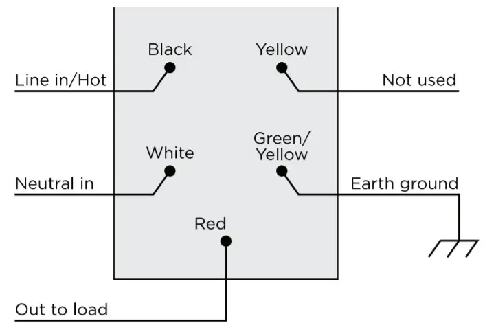
Figure 5. Single device location, without a neutral connection
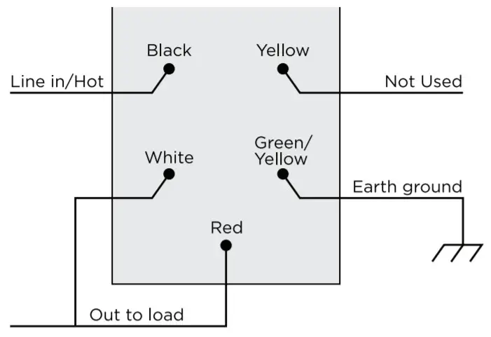
Figure 6. Multiple device locations using Auxiliary Keypad, with neutral connection (recommended)
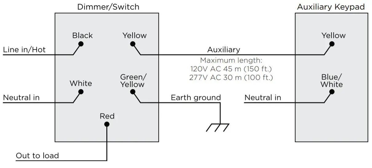
Figure 7. Multiple device locations with Auxiliary Keypad, without a neutral connection

![]() IMPORTANT! When used in conjunction with an Auxiliary Keypad (C4-KA-xx), the wire connecting the Auxiliary Keypad to the dimmer must not exceed 45 m (150 ft.) at 120V AC and 30 m (100 ft.) at 277V AC.Figure 8. Multiple device locations using Configurable Keypad, neutral required
IMPORTANT! When used in conjunction with an Auxiliary Keypad (C4-KA-xx), the wire connecting the Auxiliary Keypad to the dimmer must not exceed 45 m (150 ft.) at 120V AC and 30 m (100 ft.) at 277V AC.Figure 8. Multiple device locations using Configurable Keypad, neutral required
 report this ad
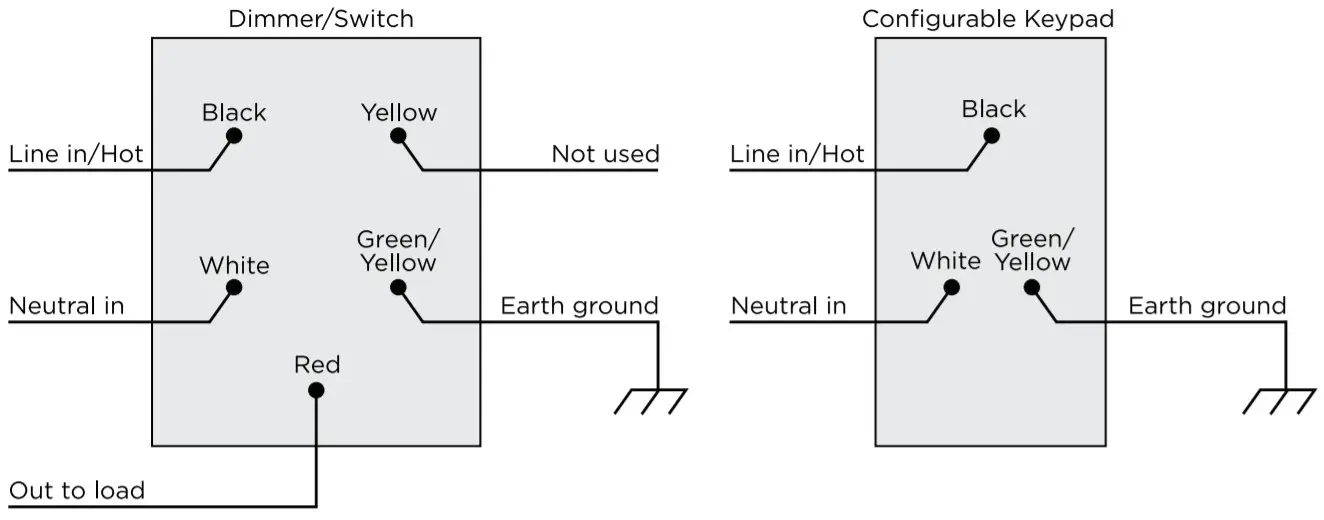
Copyright ©2020, Wirepath Home Systems, LLC. All rights reserved. Control4 and Snap AV and their respective logos are registered trademarks or trademarks of Wirepath Home Systems, LLC, dba “Control4” and/or dba “SnapAV” in the United States and/or other countries. Snap AV and Wirepath are also registered trademarks or trademarks of Wirepath Home Systems, LLC. Other names and brands may be claimed as the property of their respective owners. All specifications are subject to change without notice. 200-00308-G 2020-02-17 MS.
References
[xyz-ips snippet=”download-snippet”]