
![]()
Light Switch
User Manual

![]()
![]()
![]()
![]()
Thank you for your supportPlease read the user manual carefully before operating.Please keep the user manual for future reference.
Product Introduction
Light Switch is an intelligent device that can be remotely controlled through Z-Wave network and radio waves. In the Z-Wave network communications, light switch can be connected to any Z-Wave gateway.
When using radio waves, light switch can be used in conjunction with Z-Wave gateway. The frequency of radio waves used by gateway and switch is like this: different countries or areas, the radio frequency is different. Each light switch has a unique ID code.When we add or remove the switch from the alarm host, just place light switch in the Z-Wave network range of gateway.
Then we can easily find the switch through the device ID code. In communication with gateway, light switch not only can send signals to Z-Wave gateway, but also can receive signals from it. When touch the button on light switch, it would send signals to Z-Wave gateway, then gateway can correctly display the switch on / off state; when light switch receives signals from gateway, the switch state would be remotely switched on/off.
01
Technical Parameters
- Power: 110 – 230V AC, ±10%, 50/60Hz
- Rated Load Current: 10A
- Power consumption: 0.8W
- Power Output: 2000W
- Operating mode: touch-sensitive
- Working temperature: 0-70°C
- Wireless protocol: Z-Wave
- Wireless frequency: 908.4MHz US, 868.4MHz EU
- Wireless range: Outdoor 80 meters, indoor 45 meters
- Dimensions (Dx Wx H):EU:86mm x 86mm x 34mmUS:120mm x 74mm x 37mm
02
Technical Information
- State “on” or “off” of switch can be remotely switched through app
- State “on” or “off” of switch can be viewed through app
- Conveniently and quickly switch power supply
- Assure household electrical safety
- Can be controlled by Z-Wave Gateway
What’s in the box ?
- Light Switch 1 pcs
- Screws 4pcs
- User manual 1 pcs
03
Product Configuration
04
Installation Steps
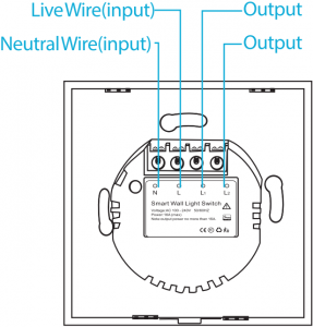
Light Switch(EU) Installation
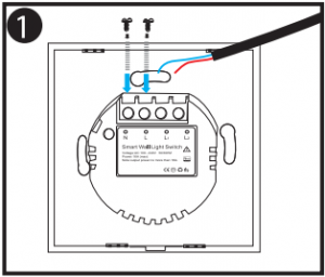
Remove the screws, connect Live wire to L,Neutral wire to N.

Screw on the screws

Connect household loads to the L1 and L2 of light switch
Light Switch(US) Installation
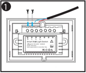
Remove the screws, connect Live wire to L,Neutral wire to N.

Screw on the screws

Connect household loads to the L1 and L2 of light switch
05
Connection Sketch Map
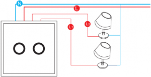
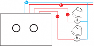
Note:
- Please disconnect the power before operation.
- Below blue wire is neutral wire (N); The red wire is live wire(L).
- In the state of electricity, do not directly touch the wiring part by hand.
- The maximum current can not exceed 16A.
06
Network Configuration
Z-Wave Network Inclusion/Exclusion/Reset
Light Switch EU/US 1CH
| Add | 1. Set Z-Wave Controller into inclusion mode2. Power on the device.3. Touch the button 3 times within 1.5s.4. The device will be entered into inclusion mode automatically. | All Led lights will be blinked with 1s inter-val until inclusion successful. |
| Remove | 1. Set Z-Wave Controller into exclusion mode2. Power on the device.3. Touch the button 3 times within 1.5s4. The Bulb will be entered into exclusion mode automatically. | All Led lights will be blinked 3 times with 0.5s interval. |
| Factory Reset 1 | 1. Power on the device.2. Keep holding touched the button for 10s until the led turn to red, then release. | |
| Product Test Mode | 1. Press and hold the button.2. Power on the device, device will enter factory product test mode | Led will blink with 100ms interval. |
Notice 1: Factory Reset will clear all Z-Wave Network data of the light switch (include home id, node id, etc…) saved in memory, and restore all configuration parameters to factory default. Please use this procedure only when the network primary controller is missing or otherwise inoperable.
07
Light Switch EU/US 2CH
| Add1 | 1. Set Z-Wave Controller into inclusion mode2. Power on the device.3. Touch any button 3 times within 1s.4. The device will be entered into inclusion mode automatically. | All Led lights will be blinked with 0.4s first and then 1s interval until inclusion successful. |
| Remove | 1. Set Z-Wave Controller into exclusion mode2. Power on the device.3. Touch any button 3 times within 1s4. The Bulb will be entered into exclusion mode automatically. | All Led lights will be blinked 3 times with 0.4s interval. |
| Factory Reset 2 | 1. Power on the device.2. Keep holding touched the button for 10s until the led turn to red, then release. | All Led lights will be light on and blink. |
| Product Test Mode | Touch any button 3 times within 1s | All Led lights will be blinked 5 times with 0.4s interval |
Notice 1: When device enters into inclusion mode, the device all functionality will be useless. The inclusion mode will be timeout after 30s, user can press the button 3 times within ls to terminate inclusion mode.
Notice 2: Factory Reset will clear all Z-Wave Network data of the light switch (include home id, node id, etc…) saved in memory, and restore all configuration parameters to factory default. Please use this procedure only when the network primary controller is missing or otherwise inoperable.
09
Associations
Light Switch EU/US 1CH
This device supports 1 association groups, and supports max 5 associated nodes in group 1. The Command Class supported by each association group is shown in the table below:
| Group | Command Class | Command |
| 1 (Lifeline) | COMMAND_CLASS_SWITCH_BINARY COMMAND_CLASS_DEVICE_RESET_LOCALLY | SWITCH_BINARY_REPORT DEVICE_RESET_LOCALLY_NOTIFICATION |
Light Switch US/EU 2CH
Root (Endpoint 0) Group
The device supports 3 association groups, and each group supports max 2 associated nodes in root group.Group 1, Lifeline – All nodes which associated in group 1(lifeline group) will receive the messages that send by device through lifeline.The Command Class supported by each association group is shown in the table below:
10
| Group | Command Class | Command |
| 1 (Lifeline) | COMMAND_CLASS_SWITCH_BINARY COMMAND_CLASS_DEVICE_RESET_LOCALLY | SWITCH_BINARY_REPORT DEVICE_RESET_LOCALLY_ NOTIFICAT ION |
| 2 (Mappingto EP 1) | COMMAND_CLASS_SWITCH_BINARY | SWITCH_BINARY_REPORT |
| 3 (Mappingto EP 2) | COMMAND_CLASS_SWITCH_BINARY | SWITCH_BINARY_REPORT |
Endpoint 1 Group
This Endpoint supports 2 groups, and each group supports max 5 associated nodes. Group 1 is endpoint 1 lifeline group. This group is mapping to group 1 in root group. The Command Class supported by each association group is shown in the table below:
| Group | Command Class | Command |
| 1 (Lifeline) | COMMAND_CLASS_SWITCH_BINARY | SWITCH_BINARY_REPORT |
| 2 | COMMAND_CLASS_SWITCH_BINARY | SWITCH_BINARY_REPORT |
Endpoint 2 Group
This Endpoint supports 2 groups, and each group supports max 5 associated nodes. Group 1 is endpoint 2 lifeline group. This group is mapping to group 1 in root group. The Command Class supported by each association group is shown in the table below:
11
| Group | Command Class | Command |
| 1 (Lifeline) | COMMAND_CLASS_SWITCH_BINARY | SWITCH_BINARY_REPORT |
| 2 | COMMAND_CLASS_SWITCH_BINARY | SWITCH_BINARY_REPORT |
Light Switch Functionality
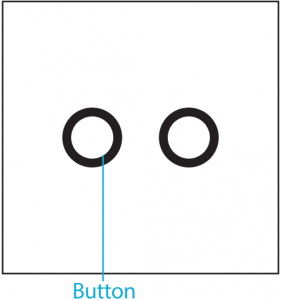
1.Switch
There are two ways for controlling the Light Switch.The one is touch button to turn on/off switch. Another is Z-Wave command class via network.The commands that operated the switch via Z-Wave Controller or Others Devices that associated it by Command Class are listed as below table.
Light Switch EU/US 1CH
| State | Command Class | Command | Value |
| ON | COMMAND_CLASS_SWITCH_BINARY | SWITCH_BINARY_SET | 0xFF |
| COMMAND_CLASS_BASIC | BASIC_SET | 0xFF | |
| COMMAND_CLASS_SWITCH_ALL | SWITCH_ALL_ON | ||
| OFF | COMMAND_CLASS_SWITCH_BINARY | SWITCH_BINARY_SET | 0x00 |
| COMMAND_CLASS_BASIC | BASIC_SET | 0x00 | |
| COMMAND_CLASS_SWITCH_ALL | SWITCH_ALL_OFF |
12
Light Switch US/EU 2CH
| State | Command Class | Command | Value |
| ON | COMMAND_CLASS_SWITCH_BINARY | SWITCH_BINARY_SET | 0xFF |
| COMMAND_CLASS_BASIC | BASIC_SET | 0xFF | |
|
OFF |
COMMAND_CLASS_SWITCH_BINARY | SWITCH_BINARY_SET | 0x00 |
| COMMAND_CLASS_BASIC | BASIC_SET | 0x00 |
2.Timing
The device also provides the function of timing, and users can turn off the device by opening this function and setting the time cycle, the setting method of which is shown in “Command Class Configuration”.
13
Advanced Configuration
Light Switch EU/US 1 CH
The device supports the controller to configure parameters of the device through Configuration Command Class, and the device has 6 parameters available for users to set according to their different needs:
1. Relay On/Off Status Saved EnableThis parameter defines the on/off status of relay is need to save or not. The status will be saved when relay status is changed if this parameter is set to ‘1’; otherwise the relay status is not saved.The Light Switch will restore the relay On/Off status previous when power on again.Parameter NumberSize (Byte) Available Settings Default value1 1 0, 1 1
2. Backlight EnableThis parameter defines the backlight state for touch button. The backlight led is on when Light Switch power on if this parameter is set to ‘1’, otherwise the backlight led is off. The default value is ‘1’.Parameter NumberSize (Byte) Available Settings Default value2 1 0, 1 1
3. Relay On/Off IndicateThis Parameter defines the relay state. The led will be turn on with pink color when the button is touched to turn on relay if this parameter is set to ‘1’; otherwise the led is off. The default value is ‘1’.
14
Parameter NumberSize (Byte) Available Settings Default value3 1 0, 1 1
4. Button Switch Function DisableSetting this configuration as ‘0’ will be disabling to turn on and off the relay by pressed button.Parameter NumberSize (Byte) Available Settings Default value4 1 0, 1 1
5. Timer EnableSetting this configuration as ‘1’ will start the timing function of the plug, and the length of time is determined by the setting of “Configuration:No.7”.This function can only provide the time to turn off device function when the device is open.Parameter NumberSize (Byte) Available Settings Default value1 1 0, 1 0
6. Time Length SettingThis configuration sets the time length for turning off the device. This configuration is only valid when “Configuration No.5” is set to ‘1’. Unit: minute. Parameter NumberSize (Byte) Available Settings Default value6 2 32767 150
15
Light Switch EU/US 2CH
The device supports the controller to configure parameters of the device through Configuration Command Class, and the device has 8 parameters available for users to set according to their different needs:
1. Relay On/Off Status Saved EnableThis parameter defines the on/off status of relay is need to save or not. The status will be saved when relay status is changed if this parameter is set to ‘1’; otherwise the relay status is not saved. The Light Switch will restore the relay On/Off status previous when power on again.Parameter NumberSize (Byte) Available Settings Default value1 1 0, 1 1
2. Backlight EnableThis parameter defines the backlight state for touch button. The backlight led is on when Light Switch power on if this parameter is set tali’, otherwise the backlight led is off. The default value is ‘1’.Parameter NumberSize (Byte) Available Settings Default value2 1 0, 1 1
3. Relay On/Off IndicateThis Parameter defines the relay state. The led will be turn on with pink color when the button is touched to turn on relay if this parameter is set to ‘1’; otherwise the led is off. The default value is ‘1’.Parameter NumberSize (Byte) Available Settings Default value3 1 0, 1 1
16
4. Root Device Controlled SettingsThis parameter defines which endpoint is mapped to root device (Endpoint 0). The valid values are explained as follows. The defaul value is ‘1’.0 – No endpoint is mapped to root endpoint1 – Endpoint 1 is mapped to root endpoint2 – Endpoint 2 is mapped to root endpoint3 – Both endpoint 1 and 2 are mapped to root endpoint.For example, assumes this parameter is set to ‘1’ (default value). Controller or other devices (such as door/window sensor, motion sensor, etc) that associated the Light Switch send a command BASIC_SET = 0xFF to Light Switch, the relay in endpoint 1 will be turned on; other relay status will not be changed.Parameter NumberSize (Byte) Available Settings Default value4 1 0-3 1
5. Button Switch Function DisableSetting this configuration as ‘0’ will be disabling to turn on and off the relay by pressed button.Parameter NumberSize (Byte) Available Settings Default value5 1 0, 1 1
6. Timer EnableSetting this configuration as ‘1’ will start the timing function of the plug, and the length of time is determined by the setting of “Configuration: No.7”.This function can only provide the time to turn off device function when the device is open.
17
Parameter NumberSize (Byte) Available Settings Default value6 1 0, 1 0
7. Channel 1 Off Time SettingThis configuration sets the time delay to turn off switch channel 1 when channel 1 is turned on. This configuration is only valid when “Configuration No.6” is set to ‘1’. Unit: minute.Parameter NumberSize (Byte) Available Settings Default value7 2 32767 0
8. Channel 2 Off Time SettingThis configuration sets the time delay to turn off switch channel 2 when channel 2 is turned on. This configuration is only valid when “Configuration No.6” is set to ‘1’. Unit: minute.Parameter NumberSize (Byte) Available Settings Default value8 2 32767 0
Multi Channel Command ClassThis device supports 2 endpoints, and both endpoints are supported the same device type, command class descript as blow:Device Type: On/Off Power SwitchSupport Command Class:1) Non-Security Include in No-SecurityControllerCOMMAND_CLASS_ZWAVEPLUS_INFO, COMMAND_CLASS_ASSOCIATION,
18
COMMAND_CLASS_ASSOCIATION_GRP_INFO,COMMAND_CLASS_MULTI_CHANNEL_ASSOCIATION,COMMAND_CLASS_SWITCH_BINARY,COMMAND_CLASS_SUPERVISION
2) No-Security Include in Security Controller:COMMAND_CLASS_ZWAVEPLUS_INFO,COMMAND_CLASS_SECURITY, COMMAND_CLASS_SECURITY_2,COMMAND_CLASS_SUPERVISION
3) Security Include in Security Controller:COMMAND_CLASS_ASSOCIATION,COMMAND_CLASS_ASSOCIATION_GRP_INFO,COMMAND_CLASS_MULTI_CHANNEL_ASSOCIATION,COMMAND_CLASS_SWITCH_BINARY,COMMAND_CLASS_SUPERVISION
Usage:All Commands must be encapsulated by Multi Channel Command Class. Two Endpoints are same device type and same control method.Endpoint 1 control method:On: SWITCH_BINARY_SET = 0xFF or BASIC_SET = 0xFF OFF:SWITCH_BINARY_SET = 0x00 or BASIC_SET = 0x00Endpoint 2 control method:On: SWITCH_BINARY_SET = 0xFF or BASIC_SET = 0xFF OFF:SWITCH_BINARY_SET = 0x00 or BASIC_SET = 0x00
19
SmartStart & 52 Security Function
SmartStart
This device supports SmartStart function. QR code printed by laser can be found on surface of product and the outside of packing box. And the full DSK code is printed can be found on the packing box.The device will enter SmartStart if the device is not included in network after power up. And then
2nd SmartStart time delay approximately 16s3rd SmartStart time delay approximately 32s4th SmartStart time delay approximately 64s5th SmartStart time delay approximately 128s6th SmartStart time delay approximately 256s7th SmartStart time delay approximately 512sAfterwards, the Smartstart mode will be auto running with 512 second interval until device is included successfully.
Security Network
The device supports the security function with and S2 + SmartStart encrypted communication. The device will auto switch to the security mode when the device included with a security controller. In the security mode, the follow commands must use security or security_2 command class wrapped to communicate, otherwise the device will not response any commands.
20
Security Keys
This device supports security levels are listed in below table:
Light Switch EU/US 1CH
| Security Levels | Support (Yes/No) |
| SECURITY_KEY_S0 | No |
| SECURITY_KEY_S2_UNAUTHENTICATED | Yes |
| SECURITY_KEY_S2_AUTHENTICATED | Yes |
| SECURITY_KEY_S2_ACCESS | No |
Light Switch EU/US 2CH
| Security Levels | Support (Yes/No) |
| SECURITY_KEY_S0 | No |
| SECURITY_KEY_S2_UNAUTHENTICATED | Yes |
| SECURITY_KEY_S2_AUTHENTICATED | No |
| SECURITY_KEY_S2_ACCESS | No |
21
Command Classes
All Supports Command Class
This device supports Z-Wave Command Class as follows:* COMMAND_CLASS_ZWAVEPLUS_INFO (V2)* COMMAND_CLASS_SECURITY_2 (V1)* COMMAND_CLASS_TRANSPORT_SERVICE (V2)* COMMAND_CLASS_VERSION (V3)* COMMAND_CLASS_POWERLEVEL (V1)* COMMAND_CLASS_ASSOCIATION (V2)* COMMAND_CLASS_MULTI_CHANNEL (V4)* COMMAND_CLASS_MULTI_CHANNEL_ASSOCIATION (V3)* COMMAND_CLASS_ASSOCIATION_GRP_INFO (V1)* COMMAND_CLASS_MANUFACTURER_SPECIFIC (V2)* COMMAND_CLASS_DEVICE_RESET_LOCALLY (V1)* COMMAND_CLASS_SWITCH_ALL (V1) [Only for 1 CH]* COMMAND_CLASS_SWITCH_BINARY (V2)* COMMAND_CLASS_CONFIGURATION (V1)* COMMAND_CLASS_SUPERVISION (V1)
22
All Security Command Class in Security Network
The Z-Wave Command Classes are secured in security network as follows:* COMMAND_CLASS_VERSION (V2)* COMMAND_CLASS_POWERLEVEL (V1)* COMMAND_CLASS_ASSOCIATION (V2)* COMMAND_CLASS_MULTI_CHANNEL (V4)* COMMAND_CLASS_MULTI_CHANNEL_ASSOCIATION (V3)* COMMAND_CLASS_ASSOCIATION_GRP_INFO (V1)* COMMAND_CLASS_MANUFACTURER_SPECIFIC (V2)* COMMAND_CLASS_DEVICE_RESET_LOCALLY (V1)* COMMAND_CLASS_SWITCH_ALL (V1) [Only for 1 CH]* COMMAND_CLASS_SWITCH_BINARY (V2)* COMMAND_CLASS_CONFIGURATION (V1)
Non-Secure Command Class in Secure Network
Unsecure Command Class which included in a secure Z-Wave Network is listed in unsecure node information.* COMMAND_CLASS_ZWAVEPLUS_INFO (V2)* COMMAND CLASS SECURITY_2 (V1)* COMMAND_CLASS_TRANSPORT_SERVICE (V2)* COMMAND_CLASS_SUPERVISION (V1)
23
Guarantee
- The Guarantee is provided by our company (hereinafter”Manufacture”)
- The Manufacturer is responsible for equipment malfunction resulting from physical defects (manufacturing or material) for 12 months from the date of its purchasing.
- During the Guarantee period, the Manufacturer shall repair or replace any defects, free of charge.
- In special cases, when the device cannot be replaced with the device of the same type (e.g. the device is no longer available in the commercial offer), the Manufacturer may replace it with a different device which has similar technical parameters as the faulty one. Such activity shall be considered as fulfilling the obligations of the Manufacturer. The Manufacturer shall not refund money paid for the device.
- The guarantee shall not cover:a. mechanical damages (cracks, fractures, cuts, abrasions, physical deformations caused by impact, falling or dropping the device or other object, improper use or not observing the operating manual);b. damages resulting from external causes, e.g.: flood, storm, fire, lightning, natural disasters, earthquakes, war, civil disturbance, force majeure, unforeseen accidents, theft, water damage, liquid leakage ,battery spill, weather conditions, sunlight, sand, moisture, high or low temperature, air pollutionc. damages caused by malfunctioning software, attack of a computer virus, or by failure to update the software as recommended by the Manufacturer.
All above is for reference only, please see the subject products.
[xyz-ips snippet=”download-snippet”]