CornuFé 110 Dual Fuel User Manual
INSTALLATION
Check the appliance is electrically safe ad gas when you have finished
11. Gas connection
Installation of this range must conform with local codes or, in the absence of local codes, with the National Fuel Gas Code, ANSI Z223.1 latest edition.
In Canada
The range must be installed in accordance with the current CGA Standard CAN/CGA-8149 – Installation Codes for Gas Burning Appliances and Equipment and/or local codes.
In the Commonwealth of Massachusetts
This product must be installed by a licensed plumber or gas fitter when installed within the Commonwealth of Massachusetts.A”T” handle type manual gas valve must be installed in the gas supply line to this appliance.
Gas supply requirements
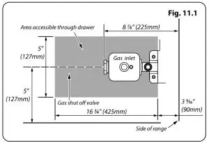
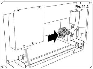
Recommended gas pipe outlet locations are shown in Fig. 11.1 and Fig. 11.2.
Provide adequate gas supply
Prior to installation, make sure that the local distribution conditions (nature of the gas and gas pressure) and the adjustment of the appliance are compatible.
A conversion kit for LP gas (Propane) is supplied with the range. When converted to LP gas, a pressure of 10″ of the water column (2.49 kPa) is required.
Make sure you are supplying your range with the correct type of gas.
We recommend that the range be converted before installation. This must be done before the range can be used on LP gas.
For proper operation, the pressure of natural gas supplied to the regulator must be between 41/2″ and 13″of water column (1.12-3.24 kPa).
For LP gas, the pressure supplied must be between 10′ and 13″of water column (2.49-3.24 kPa).
When checking for proper operation of the regulator, the inlet pressure must be at least 1″(0.25 kPa) above the manufacturer’s specified manifold pressure.
The pressure regulator located at the inlet of the range manifold must remain in the supply line, regardless of whether natural or LP gas is being used.
A flexible metal appliance connector used to connect the range to the gas supply line should have an I.D. of 1/2″ and be 5 feet in length for ease of installation.
Connect the range to the gas supply
Don’t forget to relight the pilot on other gas appliances when you turn the gas back on.
Because hard piping restricts movement of the range, the use of a CSA International-certified flexible metal appliance connector is recommended unless local codes require a hard-piped connection.
The Installation shall be made with a connector that complies with ANSI Z21.69.CSA 6.16 and using a quick disconnect device complying with ANSI Z21A1.CSA 6.9 (Fig.11.3).

If disconnection of the restraint chain is necessary, ensure the restraint is reconnected when the appliance is returned to its original installed position.NEVER If the hard piping method is used, you must carefully align the pipe; the range cannot be moved after the connection is made. To prevent gas leaks, put pipe joint compound on, or wrap pipe thread tape with Teflon* around, all male (external) pipe threads.
A. Make sure everyone operating the range knows where and how to shut off the gas supply to the range.B. Use a backup wrench on the regulator fitting to avoid damage. When installing the range from the front, remove the 90° elbow for easier installation.C. Install male ½ or ¾ flare union adapters to the NPT Internal thread of the manual shut-off valve, taking care to back up the shut-off valve to keep It from turning.D. Position the range to permit connection at the shut-off valve.E. Use a liquid leak detector at all joints and connections to check for leaks in the system. Use a product specifically manufactured for leak detection. Leak testing of the appliance should be conducted In accordance with the manufacturer’s instructions.
![]() DO NOT use a flame to check for gas leaks.
DO NOT use a flame to check for gas leaks.
When using test pressures greater than 1/2 psig (3.5 kPa) to pressure test the gas supply system of the residence, disconnect the range and individual shut off valve from the gas supply piping. When using test pressures of Vs psig (3.5 kPa) or less to test the gas supply system, simply isolate the range from the gas supply system by closing the Individual shut-off valve.
Flexible Connector
Installer: Inform the consumer of the location of the gas shut-off valve (Flg.10.4).
13. Electrical connection
Have your appliance properly Installed and grounded by a qualified technician. The installation must conform with local codes, or In the absence of local codes, In accordance with the National Fuel Gas Code, ANSI 2223.1/NFPA 54 or, in Canada, the Natural Gas and Propane Installation Code, CM 6149.1 and in addition the National Electrical Code NFPA 70 or the Canadian Electric Code, CSA C22.1.
Electrical requirements
![]() For personal safety, DO NOT use an extension cord with this appliance. Remove the house fuse or open the circuit breaker before beginning installation.
For personal safety, DO NOT use an extension cord with this appliance. Remove the house fuse or open the circuit breaker before beginning installation.
![]() WARNING Electrical Grounding Instructions. This appliance is shipped with a (four-prong) grounding plug for your protection against shock hazard and should be plugged directly into a properly grounded receptacle. DO NOT cut or remove the grounding prong from this plug.
WARNING Electrical Grounding Instructions. This appliance is shipped with a (four-prong) grounding plug for your protection against shock hazard and should be plugged directly into a properly grounded receptacle. DO NOT cut or remove the grounding prong from this plug.
![]() Prior to connecting the power cord to the wall socket, inspect the cable for any damage that may have occurred. In the event of damage please consult your electrical installer.
Prior to connecting the power cord to the wall socket, inspect the cable for any damage that may have occurred. In the event of damage please consult your electrical installer.
![]() Ensure that the power cord is routed so that it cannot become damaged during the installation.
Ensure that the power cord is routed so that it cannot become damaged during the installation.
This appliance must be supplied with the proper voltage and frequency, and connected to an individual, properly grounds branch circuit protects by a circuit breaker or time-delay fuse, as noted on the rating plate.
Wiring must conform to National Electric Codes. If the electric service provided does not meet the above specifications, have a licensed electrician install an approved outlet.
Because range terminals are not accessible after the range is in position, flexible service conduit or cord must be used.
Provide proper electrical supply
This range must be supplied with 240V 60 Hz, and connected to an individual, properly grounded branch circuit protected by a circuit breaker or time-delay fuse. If the electrical service provided does not meet the above specifications, it is recommended that a licensed electrician install an approved outlet.
Connecting using the supplied cord and plug
Your range is shipped with a 4-prong NEMA 14-50P plug to be used in a NEMA 14-50R receptacle.
Recommended electrical outlet location
When connecting using a NEMA 14-50FI receptacle, if possible position it so it can be easily accessed.
Plug the range power cord into a properly grounded wall receptacle.
Connecting if the supplied cord and plug is not suitable.
To access the electrical connections, undo the screws and remove the electrical cover (Fig. 13.1).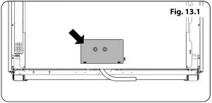
DISCONNECT THE ELECTRICAL SUPPLY.
Fitting a 3-Wire Power Cord
Disconnect the supplied power cord from the terminal block and ground post. Keep the terminal block parts; you will need them.
Insert the new power cord through the strain relief device but do not tighten the device yet.
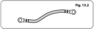
![]() Your range Is supplied with a ground strap that can be used when connecting to a three wire cord. Consult your electrician before changing the supplied cord kit (Fig. 13.2).
Your range Is supplied with a ground strap that can be used when connecting to a three wire cord. Consult your electrician before changing the supplied cord kit (Fig. 13.2).
Fit the Ground strap to the ground and center terminal of the connector block (Fig. 13.3).
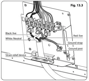
The neutral or ground wire of the power cord must be connected to the neutral terminal located in the center of the connector block. The power leads must be connected to the outside terminals (Fig. 13.3).
Fitting a 4-Wire Power Cord Disconnect the supplied power cord from the terminal block and ground post. Keep the terminal block parts; you will need them.
Insert the new power cord through the strain relief device but do not tighten the device yet.
Fit the wires to the ground post and terminal block (Fig. 13.4.)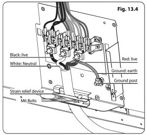
After fitting your 3 wire or 4 wire Power Cord
![]() Please Torque Tighten the Two M6 Bolts within the strain relief to 1 Nm to 1.2 Nm (0.74 ft-lb to 0.89 ft-lb)
Please Torque Tighten the Two M6 Bolts within the strain relief to 1 Nm to 1.2 Nm (0.74 ft-lb to 0.89 ft-lb)
![]() DO NOT EXCEED the Stated Torque this may cause cable damage.
DO NOT EXCEED the Stated Torque this may cause cable damage.
Final Adjustments
Make sure the connections are tight. Now tighten the strain relief device to clamp the power cord.
Refit the electrical connection cover.
Seal the Openings
Seal any openings in the %%311 behind the range and in the floor under the range when hookups are completed.
When all Connections are Completed
MAKE SURE THE FLOW OF COMBUSTION AND VENTILATION AIR TO THE RANGE IS UNOBSTRUCTED.
[xyz-ips snippet=”download-snippet”]