
![]()
CARBIDE SERIES 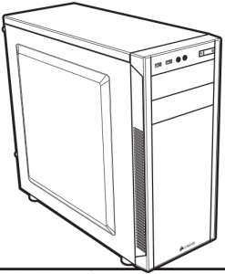

INSTALLATION GUIDE
![]()
47100 Bayside Parkway • Fremont • California • 94538 • USA | corsair.com
© 2015-2020 CORSAIR MEMORY, Inc.All rights reserved. CORSAIR, the sails logo, and Carbide Series are registered trademarks of CORSAIR in the United States and/or other countries. All other trademarks are the property of their respective owners. Product may vary slightly from those pictured.
49-001402 AB
Congratulations!
Thank you for purchasing the Carbide Series 100R Silent Edition Mid-Tower PC Case.
The Carbide Series 100R Silent Edition mid tower PC case lets you hide a high-powered, killer gaming rig inside of a chassis that would look at home in any professional environment. It’s easy to customize with plenty of tool-free installation options, highly expandable with extra fan ports and drive bays to support SSDs, and performance-minded with USB 3.0 support and direct airflow to the GPU. The Carbide Series 100R Silent Edition looks simple and elegant from the outside, but the inside provides you with all the options you need for an amazing system.
1
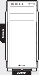
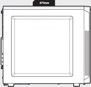
Case Specifications
Length ………….. 471mmWidth …………… 200mmHeight ………….. 430mmWeight ………….. 4.9kg
Maximum GPU length:Top slots ………………. 414mmLower slots ……………. 275mmMaximum CPU cooler height … 150mmMaximum PSU length ………. 260mm
2
Accessory Kit Contents
a 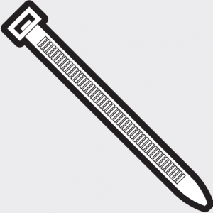 x4 b
x4 b  x10 c
x10 c  x16
x16
Cable ties MBD/HDD screws SSD/ODD screws
d  x4 e
x4 e  x16 f
x16 f  x4
x4
SSD pan head screws Short fan screws Long fan screws
g  x1
x1
Motherboard standoff
3
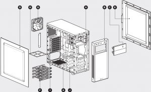
Case Features
A I/O Panel (x2 USB 3.0, Headphone/Mic, and Power/Reset)B Removable front fasciaC x2 Tool-free removable ODD coversD Solid side panelE Solid side panelF x4 Tool-free 3.5″ hard drive trays with 2.5″ compatibilityG 3-pin 120mm FanH Bottom PSU dust filterI PCI-e screw railJ x1 Tool-free 3.5″ hard drive cage with 2.5″ compatibilityK CPU backplate cutout
4
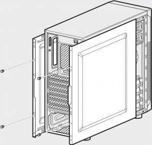
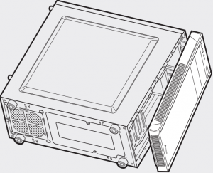
1. Removing the Side Panels
Simply remove the thumbscrews then slide the side panels back and out.
Note: CORSAIR recommends removing both side panels and setting them aside when building your system to avoid accidental damage. Both side panels are interchangeable and should be removed to reduce clutter.
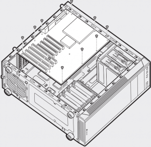
2. Installing the Motherboard
First, install your motherboard’s I/O shield (see your motherboard’s manual for guidance).
Align your motherboard with the pre-installed standoffs.
Use the provided screws b to secure the motherboard to the motherboard tray.
5
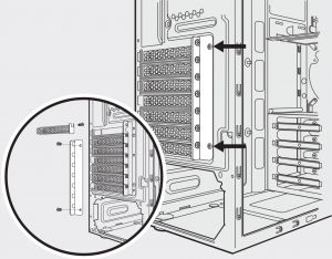
3. Installing PCI-e/PCI Card(s)
Remove thumbscrews and corresponding slot cover(s).
Install the add-on card and secure with thumbscrews.
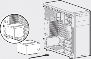
4. Installing the PSU (Power Supply Unit)
Position the PSU on the bottom of the case then align the case holes and secure the PSU with screws provided with your power supply.
6
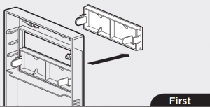
5. Removing the Front Fascia
To remove the front fascia (front panel), grasp the tab located at the bottom fascia and pull outward.
6. Installing an ODD (Optical Disk Drive)
First, remove the front panel 5.25″ drive bay cover then slide the ODD into the drive bay until the tool-free latch clicks, securing the drive. To release an optical drive, push in the tool-free tab then pull the drive outward.

7
7. Installing SSDs and HDDs
The four included drive trays support both 3.5″ and 2.5″ devices.
To install a 3.5″ HDD, pull the drive tray from each side to extend the mounting points. Next, place your HDD onto the tray and push the drive back to a close. No screws are necessary to secure the drive onto the tray.
To install a 2.5″ SSD, place the drive on the tray and use the provided screws c to install the SSD.

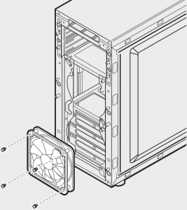
8. Installing a Second Front Fan
To install an additional 120mm or 140mm fan, remove the front fascia (step 5) then use the provided long fan screws f to mount the new fan.
Note: To maximize airflow you may install either x2 120mm or x2 140mm fans in the front of the chassis.
8
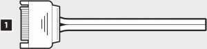
9. Powering the Case Fans
- Connect the SATA power connector to the PSU SATA power cable.
- Connect the 3 or 4-Pin fan connecter to the case fan header.
- Push the fan speed selector button on your case to toggle fan speed.


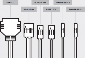
10. Installing the Front I/O Connectors
See your motherboard’s manual for front panel header locations and pin-outs.
9
Frequently Asked Questions
1. How do I remove the I/O Panel?If needed, you can uninstall your I/O panel by removing the front fascia (step 5) then unscrewing the 2 screws at each side of panel. (see drawing)
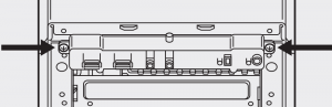
2. Does the polarity matter with the I/O panel’s power and reset header?No, only the LED headers.
3. Who should I contact if I received my case damaged or one of the fans is no longer working?Please go to support.corsair.com and request an RMA so that we can replace the damaged part(s).
4. Where can I mount a fan?
|
Fan Mount Locations |
|
| Front | x2 120mm or x2 140mm |
| Top | x |
| Rear | 120mm |
| Bottom | x |
| Side | x |
| Mid | x |
To learn more about this case visit the product page at corsair.com.
10

NOTE ON ENVIRONMENTAL PROTECTIONAfter the implementation of the European Directive 2012/19/EU in the national legal system, the following applies:— Electrical and electronic devices may not be disposed of with domestic waste.— Consumers are obligated by law to return electrical and electronic devices at the end of their service lives to the public collecting points set up for this purpose of point of sale. Details to this are defined by the national law of the respective country.This symbol on the product, the instruction manual or the package indicates that a product is subject to these regulations. By recycling, reusing the materials or other forms of utilizing old devices, you are making an important contribution to protecting our environment.

This equipment has been tested and found to comply with the limits for a Class B digital device, pursuant to part 15 of the FCC Rules. These limits are designed to provide reasonable protection against harmful interference in a residential installation. This equipment generates, uses and can radiate radio frequency energy and, if not installed and used in accordance with the instructions, may cause harmful interference to radio communications. However, there is no guarantee that interference will not occur in a particular installation. If this equipment does cause harmful interference to radio or television reception, which can be determined by turning the equipment off and on, the user is encouraged to try to correct the interference by one or more of the following measures:– Reorient or relocate the receiving antenna.– Increase the separation between the equipment and receiver.– Connect the equipment into an outlet on a circuit different from that to which the receiver is connected.– Consult the dealer or an experienced radio/TV technician for help.
FCC Caution: Any changes or modifications not expressly approved by the party responsible for compliance could void the user’s authority to operate this equipment.(1) this device may not cause harmful interference, and(2) this device must accept any interference received, including interference that may cause undesired operation.
This Class B digital apparatus meets all requirements of the CanadianInterference-Causing Equipment Regulations.CAN ICES-3(B)/NMB-3(B).

CORSAIR MEMORY, Inc. declares that this equipment is in compliance with Directive 2011/65/EU. A copy of the original declaration of conformity can be obtained at“corsair.com/ documentation”. Operating Temperature: 0°C ~ + 40°C
The Authorized Representative in EuropeCORSAIR MEMORY, BV Wormerweg 8,1311 XB, Almere, Netherlands
References
[xyz-ips snippet=”download-snippet”]