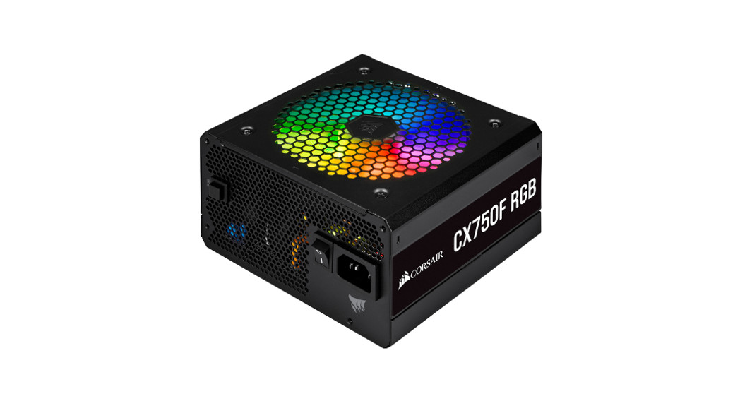
CX-F RGB SERIES™CX550F CX650F CX750FRGB ATX Power Supply
INTRODUCTION
Congratulations on the purchase of your new CORSAIR CX-F RGB Series ATX Power Supply!CORSAIR CX-F RGB Series fully modular power supplies deliver reliable 80 PLUS Bronze efficient power to your system, alongside vibrant customizable lighting from a 120mm RGB fan boasting eight RGB LEDs. Easily cycle through seven preset lighting modes, or connect to a CORSAIR iCUE RGB Lighting Controller or compatible motherboard to unlock advanced lighting control over eight individually addressable LEDs.
SAFETY AND PROTECTION
- Over-voltage protection (OVP)Over-voltage protection for the 12V, 5V, and 3.3V DC outputs is required to comply with the ATX specification. OVP shuts down the PSU in the event that the DC outputs exceed a set level, determined by the PSU manufacturer.
- Over-current protection (OCP)The CX-F RGB Series features OCP on the 3.3V, 5V, and 12V rails. OCP ensures that the output of the DC voltage rails remains within safe operating limits.
- Over-temperature protection (OTP)OTP ensures that the PSU will shut down when the internal temperature reaches a set point. This is usually a result of internal current overloading or a fan failure.
- Short-circuit protection (SCP)A short-circuit is defined as any output impedance of fewer than 0.1 ohms. Amongst other things, SCP ensures that the PSU shuts down should the 3.3V, 5V, and 12V rails short to any other rail, or to the ground. It also ensures that no damage should occur to the unit or your PC’s components in the event of a short.
CX750F RGB INCLUDED HARDWARE AND SPECIFICATIONSDimensions: 150mm (W) x 86mm (H) x 140mm (L)Package contents: Power supply, AC cable, DC cables, mounting screws, safety leaflet
| CORSAIR CX750F RGB POWER TABLE | MAX LOAD | MAX OUTPUT | ||
| MODEL | RPS0135 | +3.3V | 20A | 130W |
| PART NO. | CP-9020218/CP-9020227 | +5V | 20A | |
| AC INPUT RATING | 100–240V | +12V | 62.5A | 750W |
| INPUT CURRENT | 10A–5A | -12V | 0.3A | 3.6W |
| FREQUENCY | 47–63Hz | +5Vsb | 3A | 15W |
| TOTAL POWER: 750W |
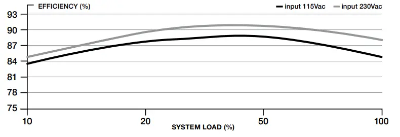
CORSAIR CX750F RGB POWER SUPPLY EFFICIENCY
CORSAIR CX750F RGB POWER SUPPLY FAN NOISE CURVE
| Qty | CORSAIR CX750F RGB cable information | Total length | |
| 1 | ATX 24 pin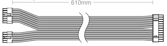 |
Connectors per cable | 610mm(± 10mm) |
| 1 | |||
| Total connectors | |||
| 1 | |||
| 2 | EPS/ATX12V 8 pin (4+4) |
Connectors per cable | 650mm(± 10mm) |
| 1 | |||
| Total connectors | |||
| 2 | |||
| 2 | PCIe 8 pin (6+2) |
Connectors per cable | 750mm(± 10mm) |
| 2 | |||
| Total connectors | |||
| 4 | |||
| 2 | SATA (4 SATA) |
Connectors per cable | 800mm(± 10mm) |
| 4 | |||
| Total connectors | |||
| 8 | |||
| 1 | PATA |
Connectors per cable | 750mm(± 10mm) |
| 4 | |||
| Total connectors | |||
| 4 | |||
| 1 | iCUE RGB |
Connectors per cable | 500mm(± 10mm) |
| 1 | |||
| Total connectors | |||
| 1 | |||
| 1 | iCUE RGB to ARGB |
Connectors per cable | 300mm(± 10mm) |
| 1 | |||
| Total connectors | |||
| 1 |
CX650F RGB INCLUDED HARDWARE AND SPECIFICATIONSDimensions: 150mm (W) x 86mm (H) x 140mm (L)Package contents: Power supply, AC cable, DC cables, mounting screws, safety leaflet
| CORSAIR CX750F RGB POWER TABLE | MAX LOAD | MAX OUTPUT | ||
| MODEL | RPS0134 | +3.3V | 20A | 130W |
| PART NO. | CP-9020217/CP-9020226 | +5V | 20A | |
| AC INPUT RATING | 100–240V | +12V | 62.5A | 750W |
| INPUT CURRENT | 10A–5A | -12V | 0.3A | 3.6W |
| FREQUENCY | 47–63Hz | +5Vsb | 3A | 15W |
| TOTAL POWER: 650W |
CORSAIR CX650F RGB POWER SUPPLY EFFICIENCY

CORSAIR CX650F RGB POWER SUPPLY FAN NOISE CURVE
| Qty | CORSAIR CX650F RGB cable information | Total length | |
| 1 | ATX 24 pin |
Connectors per cable | 610mm(± 10mm) |
| 1 | |||
| Total connectors | |||
| 1 | |||
| 2 | EPS/ATX12V 8 pin (4+4) |
Connectors per cable | 650mm(± 10mm) |
| 1 | |||
| Total connectors | |||
| 2 | |||
| 2 | PCIe 8 pin (6+2) |
Connectors per cable | 750mm(± 10mm) |
| 2 | |||
| Total connectors | |||
| 4 | |||
| 1 | SATA (4 SATA) |
Connectors per cable | 800mm(± 10mm) |
| 4 | |||
| Total connectors | |||
| 4 | |||
| 1 | SATA (3 SATA)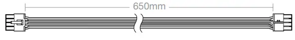 |
Connectors per cable | 700mm(± 10mm) |
| 3 | |||
| Total connectors | |||
| 3 | |||
| 1 | PATA |
Connectors per cable | 750mm(± 10mm) |
| 4 | |||
| Total connectors | |||
| 4 | |||
| 1 | iCUE RGB |
Connectors per cable | 500mm(± 10mm) |
| 1 | |||
| Total connectors | |||
| 1 | |||
| 1 | iCUE RGB to ARGB |
Connectors per cable | 300mm(± 10mm) |
| 1 | |||
| Total connectors | |||
| 1 |
INSTALLING YOUR NEW CX-F RGB SERIES POWER SUPPLY
Step 1: Removing your existing PSUIf you are building a new system, skip to Step 2.
- Disconnect the AC power cord from your wall outlet or UPS and from the existing power supply.
- Disconnect all the power cables from your video card, motherboard, and all other peripherals.
- Follow the directions in your chassis manual and uninstall your existing PSU.
- Proceed to Step 2.
Step 2: Installing the new power supply
- Make sure the power supply’s AC power cable is not connected.
- Follow the directions in your chassis manual and install the power supply with the screws provided.
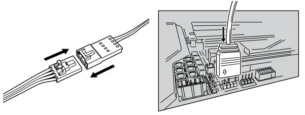
- Connect the 24-pin (ATX) cable to the motherboard. Connect the eight-pin +12V (EPS12V) cable to the motherboard.a. If your motherboard has an eight-pin +12V socket, connect the eight-pin cable directly to your motherboard.b. If your motherboard has a four-pin socket, detach the four-pin from the eight-pin cable, and then plug this four-pin cable directly into your motherboard.c. Some motherboards will require a mix of 8+4 pins, use as many EPS12V cables as necessary, and do not mistake them for PCIe cables.
- Connect the peripheral cables, PCI-Express cables, and SATA cables.a. Connect the SATA cables to your SATA SSD or hard drive’s power sockets.b. Connect the PCI-Express cables to the power sockets of your PCI-Express video cards if required.c. Connect the peripheral cables to any peripherals requiring a 4-pin connector.d. Make sure all the cables are tightly connected. Be sure to save any unused modular cables for future component additions.
- Connect the AC power cord to the power supply and turn it on by pushing the switch to the ON position (marked with “I”).
CONTROLLING THE RGB FAN IN YOUR NEW PSU
The CX-F has the ability to be controlled by CORSAIR’s iCUE software, through a compatible motherboard’s +5V ARGB header, or manually using the RGB button on the PSU.Note: Before plugging or unplugging the RGB cable, please ensure your computer is shut down and the power switch on the back of the PSU is turned to the “off” position.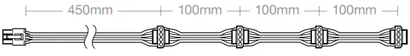
For iCUE control
1. Plug iCUE RGB cable into the PSU.2. Plug another end of the cable into a compatible corsair RGB Lighting Controller’s (Commander PRO or Lighting Node PRO) 6-port RGB hub.3. Select SP RGB PRO/CX-F Series PSU in the Lighting Setup tab.Note: The 6-port hub requires devices to be plugged in sequentially, and all fans plugged into the hub must be of the same type or you may experience lighting issues.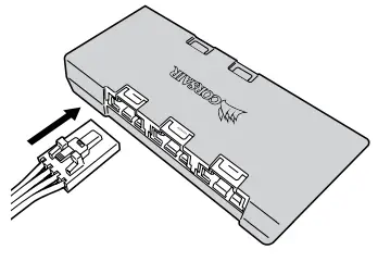 Download iCUE at:www.corsair.com/downloads
CONTROLLING THE RGB FAN IN YOUR NEW PSU
For motherboard control
- Plugin the iCUE RGB cable.
- Attach the ARGB motherboard adapter to the iCUE cable.
- Plug into the ARGB header on a compatible motherboard.
- Consult your motherboard’s manual on which software to install for the ARGB header to function properly.

For manual, push-button controlTo cycle through lighting modes:> Press and hold the button until the lighting mode changes (about three seconds).To cycle through colors (if the mode is not rainbow):> Short-press the button.Modes:
- Rainbow wave
- Rainbow
- Rainbow breathe
- Rainbow blink
- Sequential
- Solid
- Single blink
- Pulse
- Off
 report this ad
Note: Push-button control will not work if PSU is in software control mode.
| WEB: corsair.comPHONE: (888) 222-4346SUPPORT: support.corsair.com | BLOG: corsair.com/blogFORUM: forum.corsair.comYOUTUBE: youtube.com/corsairhowto | |
| © 2020 CORSAIR MEMORY Inc. All rights reserved. CORSAIR and the sails logo are registered trademarks in the United States and/or other countries. All other trademarks are the property of their respective owners. Product may vary slightly from those pictured. 49-002065 AACORSAIR MEMORY, BV | Wormerweg 8, 1311 XB, Almere, Netherlands |  |
References
[xyz-ips snippet=”download-snippet”]