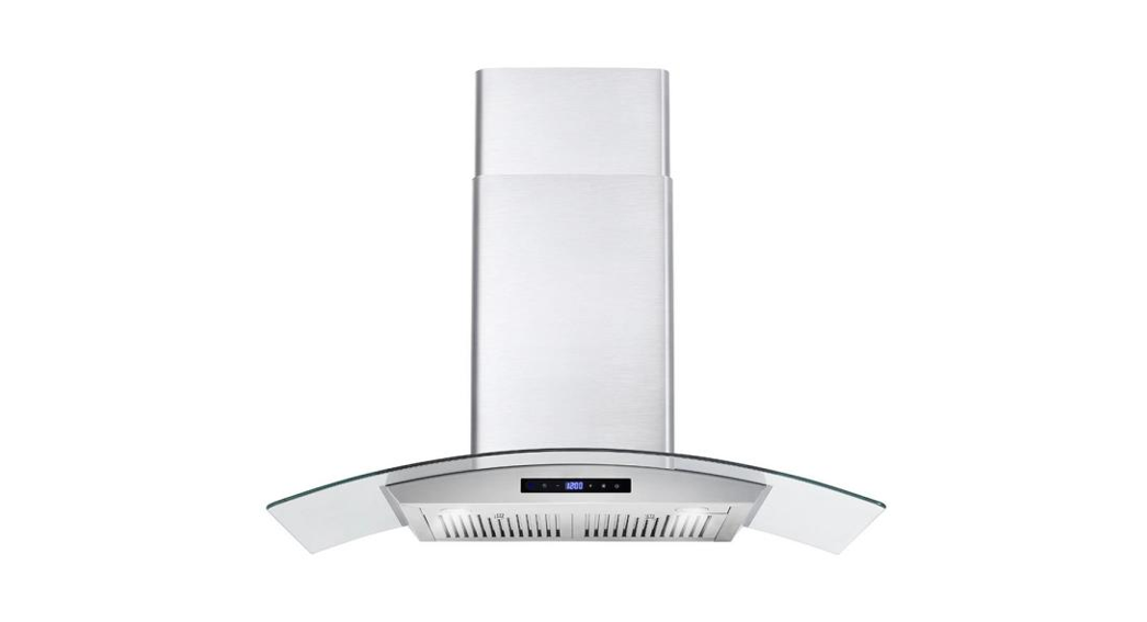
 APPLIANCESINSPIRING THE WORLD’S KITCHENWALL MOUNTRANGE HOOD
| COS-63175COS-63190COS-63175SCOS-63190S | COS-668WRC75COS-668WRC90COS-668WRCS75COS-668WRCS90 | COS-668A750COS-668A900COS-668AS750COS-668AS900 |
IMPORTANT SAFETY INSTRUCTIONSCarefully read the following Important information regarding installation safety and maintenance. Keep these instructions for future reference.INSTALLATION GUIDE & USER MANUAL
THANK YOU FOR YOUR PURCHASEThank you for your purchase. We know that you have many brands and products to choose from and we are honored to know that you have decided to take one of our products into your home and hope that you enjoy it.COSMO appliances are designed according to the strictest safety and performance standards for the North American market. We follow the most advanced manufacturing philosophy. Each appliance leaves the factory after thorough quality inspection and testing. Our distributors and our service partners are ready to answer any questions you may have regarding how to install, use and care for your products. We hope that this manual will help you learn to use the product in the safest and most effective manner.If you have any questions or concerns, please contact the dealer from whom you purchased it, or contact our Customer Support at 1-888-784-3108.
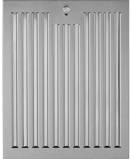
STAINLESS STEEL BAFFLE FILTERS
 |
 |
About Your New FiltersStainless Steel Baffle Filters do not need finings w mesh inside of the filters and are completely constructed out of stainless steel. The stainless steel construction Sanwa them to be used again after being cleaned or going through the dishwasher.How do Baffle Filters Work?They function by forcing the grease-filled air to quickly and continuously change direction as it passes through the filler. The grease is unable to change direction as fast as the 3W carrying them, they end up getting caught on the metal blades and then trapped into the fitter tray. These Niers are both efficient and require less maintenance.SEE PAGE 13 FOR INSTRUCTIONS ON INSTALLING FILTERS
IMPORTANT SAFETY INSTRUCTIONSRead all instructions before using this appliance.Save these instructions for future references Approved for residential appliances For residential use only
![]() CAUTIONFOR GENERAL VENTILATING USE ONLY. DO NOT USE TO EXHAUST HAZARDOUS OR EXPLOSIVE MATERIALS OR VAPORS.
CAUTIONFOR GENERAL VENTILATING USE ONLY. DO NOT USE TO EXHAUST HAZARDOUS OR EXPLOSIVE MATERIALS OR VAPORS.![]() CAUTIONTo reduce the risk of fire and to properly exhaust air, do not vent exhaust air into spaces within walls, ceilings, attics, crawl spaces, or garages.
CAUTIONTo reduce the risk of fire and to properly exhaust air, do not vent exhaust air into spaces within walls, ceilings, attics, crawl spaces, or garages.![]() WARNINGTO REDUCE THE RISK OF FIRE, USE ONLY METAL DUCTWORK. Install this hood in accordance with all requirements specified.
WARNINGTO REDUCE THE RISK OF FIRE, USE ONLY METAL DUCTWORK. Install this hood in accordance with all requirements specified.![]() WARNINGTO REDUCE THE RISK OF FIRE, ELECTRIC SHOCK, OR INJURY TO PERSONS, OBSERVE THE FOLLOWING:
WARNINGTO REDUCE THE RISK OF FIRE, ELECTRIC SHOCK, OR INJURY TO PERSONS, OBSERVE THE FOLLOWING:
- Use this unit only In the manner intended by the manufacturer. If you have questions, contact the manufacturer
- Before servicing a leaning unit, switch power off at the service panel and lock service panel disconnecting means to prevent power from being switched on accidentally. When the service disconnecting means cannot be locked, securely fasten a prominent warning device, sud) as a tag, to the service pang.
- Installation Work and Electrical Wiring Mug Be Done By Qualified Person(s) In Accordance With All Applicable Codes & Standards, Including Fire-rated Construction.
- Sufficient air is needed for proper combustion and exhausting of gases through the flue (chimney) of fuel-burning equipment to prevent back-drafting. Follow the heating equipment manufacturers’ guidelines for all safety standards such as those published by the National Fre Protection Association (NFPA), the American Society for Heating, Refrigeration and Air Conditioning Engineers (ASHRAE), and the local code authorities.
- When cutting or drilling into a wall or ceiling, do not damage electrical wiring and other hidden
- Ducted systems must always be vented to the outdoors.
![]() WARNINGTo Reduce The Risk Of Fire Or Electric Shock, Do Not Use This IRKS With Any External Solid State Speed Control Device.
WARNINGTo Reduce The Risk Of Fire Or Electric Shock, Do Not Use This IRKS With Any External Solid State Speed Control Device.![]() WARNINGGROUNDING INSTRUCTIONSThis appliance must be grounded.In the event of an electrical short circuit, grounding reduces the risk of electric shock by providing an escape wire for the electric current. This appliance is equipped with a cord having a grounding wire with a grounding plug. The plug must be plugged into an outlet that is properly installed and grounded.WARNINGIMPROPER GROUNDING CAN RESULT IN A RISK OF ELECTRIC SHOCK.Consult a qualified electrician if the grounding instructions are not completely understood, or if doubt exists as to whether the appliance is properly grounded.Do not use an extension cord. If the power supply cord is too short, have a qualified electrician install an outlet near the appliance.
WARNINGGROUNDING INSTRUCTIONSThis appliance must be grounded.In the event of an electrical short circuit, grounding reduces the risk of electric shock by providing an escape wire for the electric current. This appliance is equipped with a cord having a grounding wire with a grounding plug. The plug must be plugged into an outlet that is properly installed and grounded.WARNINGIMPROPER GROUNDING CAN RESULT IN A RISK OF ELECTRIC SHOCK.Consult a qualified electrician if the grounding instructions are not completely understood, or if doubt exists as to whether the appliance is properly grounded.Do not use an extension cord. If the power supply cord is too short, have a qualified electrician install an outlet near the appliance.![]() WARNINGTO REDUCE THE RISK OF INJURY TO PERSONS, IN THE EVENT OF A RANGE TOP GREASE FIRE, OBSERVE THE FOLLOWING:A• SMOTHER FLAMES with a dose-fitting lid, cookie sheet, or another metal tray, then turn off the gas burner or the electric element. BE CAREFUL TO PREVENT BURNS. If the flames do not go out immediately, EVACUATE AND CALL THE FIRE DEPARTMENT.B• NEVER PICK UP A FLAMING PAN -you may be burned. DO NOT USE WATER including wet dishcloths or towels -a violent steam explosion will result.Always leave safety grits and fitters in place. Without these components. operating blowers could catch onto hair. fingers and loose clothing. The manufacturer declines all responsibility in the event of failure to observe the instructions given here for installation. maintenance and suitable use of the product The manufacturer further declines all responsibility for injury due to negligence and the warranty of the unit automatically expires due to improper maintenance.
WARNINGTO REDUCE THE RISK OF INJURY TO PERSONS, IN THE EVENT OF A RANGE TOP GREASE FIRE, OBSERVE THE FOLLOWING:A• SMOTHER FLAMES with a dose-fitting lid, cookie sheet, or another metal tray, then turn off the gas burner or the electric element. BE CAREFUL TO PREVENT BURNS. If the flames do not go out immediately, EVACUATE AND CALL THE FIRE DEPARTMENT.B• NEVER PICK UP A FLAMING PAN -you may be burned. DO NOT USE WATER including wet dishcloths or towels -a violent steam explosion will result.Always leave safety grits and fitters in place. Without these components. operating blowers could catch onto hair. fingers and loose clothing. The manufacturer declines all responsibility in the event of failure to observe the instructions given here for installation. maintenance and suitable use of the product The manufacturer further declines all responsibility for injury due to negligence and the warranty of the unit automatically expires due to improper maintenance.![]() WARNINGUnplug or disconnect the appliance from the power supply before servicing.
WARNINGUnplug or disconnect the appliance from the power supply before servicing.
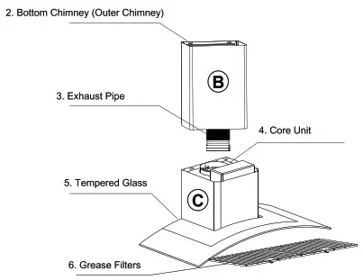
PARTS DIAGRAM
668WRC75 – 668WRC90 – 668WRCS75 – 668WRCS90 668A750 – 668A900 – 668AS750 – 668AS900 (Units with Glass Visor)
 |
 |
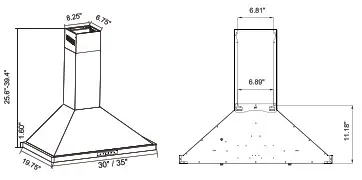
PARTS DIAGRAM
63175/63190 – 63175S/63190S
 |
 |
INSTALLATION REQUIREMENTS
- Do not install the range hood near open doors and windows to avoid reduced performance. (Fig.1)
- Install the range hood directly above the cooktop. The optimal distance between the cooktop and the lower edge of the range hood Is 24′ to 36′. (Fig.2) Install at the height appropriate to your ceiling. Make a chimney reaches the ceiling. If your ceiling leaves the hoed a few inches higher or lower than 24′ to 36″ you can still Install without a major loss of performance.
- For optimal performance. do not over-extend the exhaust tube and avoid unnecessary Mincing. (F19.3)
- After hangig the unk on the wal. ensure the range hood is straight and level. (Fig.4)
- The air outlet met to be a comma.] to chimney flumes or combustion gas ducts. Under no circumstances should the ae meter be connected to ventilation ducts for rooms in which fuel’humin9 anal: antes we installed.

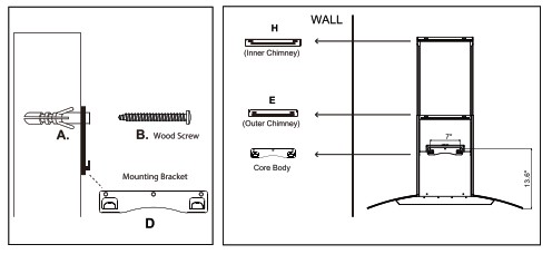
PARTS LIST

| A• 11 pcs 2/8″ x 13/8″ Plastic AnchorsB• 11 pcs 1/8″ x 1 7/8″ Screws (48mm)C• 4 pas 1/8″X3/8″ Screws panneD• Core Unit Bracket (Main Body) | E• Outer Chimney Cover BraciceiF• 6 in. Round Aluminum DuctG• pickup H. Inner Chimney Cover Bracket |
Note: Hardware, number of screws, anchors, and accessories will vary based on the product model.
RANGE HOOD INSTALLATION
Preparing Your Wall / Mounting Instructions
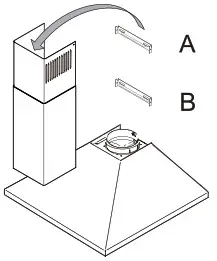
Step 1:Place the range hood on the wall and mark the position where you want to install it. A height of 24″ to 36″ from the cooktop is recommended for optimal performance. Install at the height appropriate for your ceiling. You may Install higher if needed. Make sure the chimney can still reach the ceiling. If your ceiling leaves the hood a few inches higher or lower than 24″ to 36″ you can still install it without a major loss of performance. There are 3 included brackets. Start your measurements from the top down to make sure the chimney reaches the ceiling with no gap if desired.* If you intend to run your ducting through the back wall behind the hood, it is not necessary for the chimney to touch the ceiling.Step 2:A. Find the Core Unit Bracket (D) that will hold the bath of the range hood. Mark the locations on the wall with a pencil or marker.B. Drill a 5/16″ (8mm) hole at each marked location.C. Insert wall anchors into each hole, gently tapping In place.D. Take the Core Unit Bracket ( Part 0) that will hold the range hood and firmly tighten with 3 wood screws (Part B) Into the anchors.Secure range hood by hanging on the bracket.
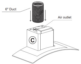
Step 3: Locate the 6″ round aluminum duct (F) and attach it to the top air outlet on the main body of the range hood with HVAC foil tape (not included). Make sure it is connected tightly.Step 4: Place the bottom of the Outer Chimney into the Core Body’s seating located near the vent hole. Then Insert the Inner Chimney cover into the Outer Chimney Cover. Note that the Inner Chimney cover must slide into the Outer Chimney covers orientation slot. (see step 7 for mounting bracket install)Step 5:A• Extend the inner chimney cover to the height at which it will touch the ceiling. Using a pencil, place a small mark on each side of the chimney cover which is level with the screw holes of the chimney. Now slide the inner chimney cover down.B• Using a pencil, place a small mark on the wall on each side of the chimneyC• Align the middle of the Inner chimney bracket (H) with the drawn line and make a mark where each screw hole in your wall will need to be drilled for mounting of the bracket.D• Drill 1/4″ holes at each marked locationThe drilled hole should be slightly smaller than the diameter of the anchor.E• Insert anchors into each drilled hole.F• Align Inner chimney bracket (H) with the drilled holes and firmly screw it into place.
 |
 |
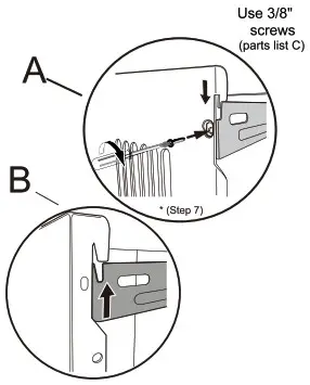 |
Step 6:Extend the 6″ Duct to the vent pipe of your building or outside. For optimal performance try to minimize bending of the duct.Step 7:Mount outer chimney bracket (E) to the wall appropriate to the height of the outer chimney. Use the hooks on the bracket to mount the bottom chimney. Extend Inner Chimney until it touches the ceiling. Align sides with Inner Chimney Mounting Bracket (H)(already mounted to the wall) and firmly screw sides of Inner Chimney to the bracket with 3/8″ screws (C in the parts list).• If you intend to run your ducting through the back wall behind the hood, it is not necessary for the chimney to touch the ceiling.
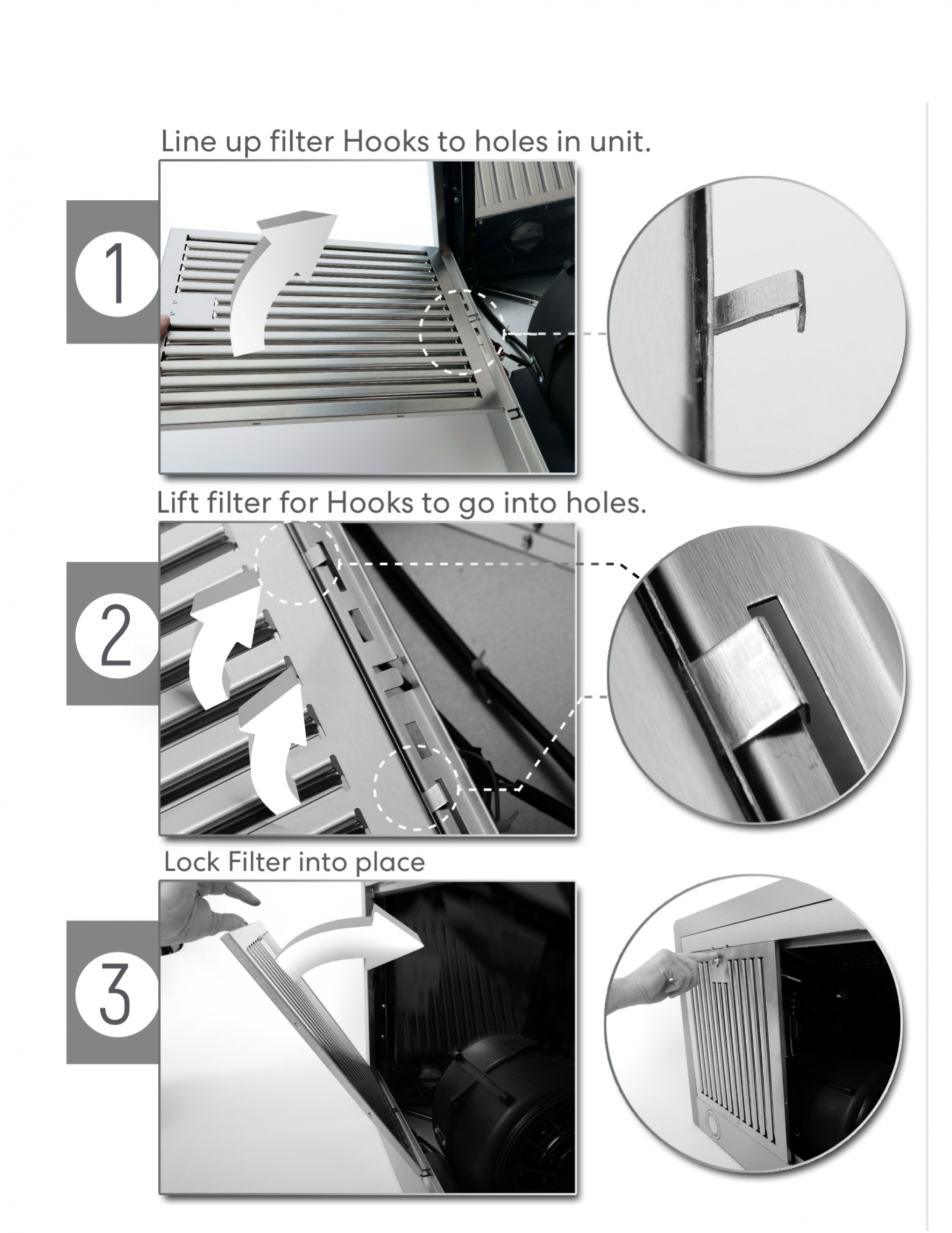
 Step 8:Insert and install filters according to the diagram on Next Page.Start at 90°Angle and line up the hooks on the filter with the rectangular slots on the range hood. Lift the filter up and push the button on filters to allow it to lock into place.
BAFFLE FILTER INSTALLATION
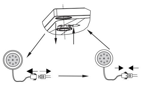
RECIRCULATING CHARCOAL FILTERS
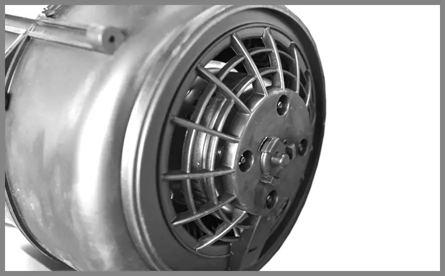
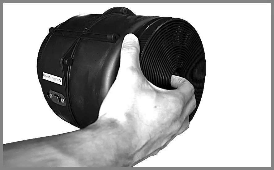
Skip this page if you are installing a Ducted Range Hood. Charcoal Filters are only included with Ductless ModelsStep 1: Remove the ARC-FLOW Baffle Filters.Step 2: Locate the motor [pictured below) and align one of the filters with the right side of the motor.
 |
 |
Step 3: Twist and lock the filter into place.Step 4: Repeat Steps 2-3 on the left side of the motor.
 |
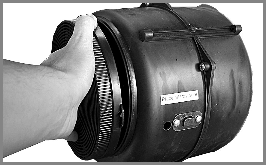 |
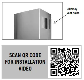
Step 5: Reinstall the ARC-FLOW Baffle Filters back into place.NOTE: Chimney vent holes must be open and visible for the filtered air to recirculate.
 |
It is recommended that the charcoal filter be replaced every 4-6 months. Charcoal filter replacements are available for purchase at: www.coamoappliances.com. Charcoal Filter Kit Part* CFK1-TM
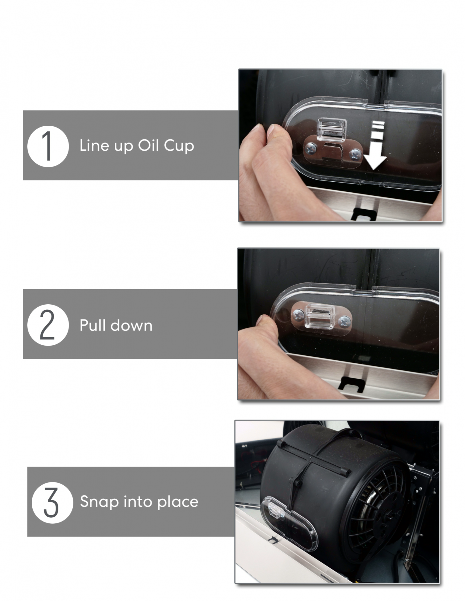
OIL CUP INSTALLATION
COMPATIBLE WITH MODELS:
| COS-63175 | COS-668A750 | COS-668WRC75 |
| COS-63190 | COS-668A900 | COS-668VVRC90 |
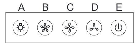 A• Light. Press to turn the light on / off.B• Highest Fan SettingC• Medium Fan SettingD• Lowest Fan SettingE• Power Button. Press to turn unit on / off.When shutting off, press once to delay shut-off for 1 minute, or press twice to shut off immediately.
SOFT-TOUCH INSTALLATION
COMPATIBLE WITH MODELS:
| COS-668WRCS75 | COS-668WRCS90 |
| COS-668AS750 | COS-668AS900 |
| COS-63175S | COS-63190S |
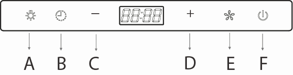
A• Light. Press to turn the light on / off.B• Timer ButtonC• Minus Button (Fan Speed)D• Plus Button (Fan Speed)E• Fan Power Button (Starts Max Fan Speed)F.• Power Button. Press to turn unit On/OffNote: When Fan is ON + or – will increase or decrease fan speed.
 Setting the Clock
- Hold Timer Button for 3 SecondsUse Light Button (A) to set MinutesUse Fan Speed Button (E) to set Hours
- Once time is set, press the Timer button to complete.
- After setting the time, leave the unit alone for 5 seconds for the changes to save.
Setting the Timer
- Turn the fan on and set it to desired fan speed.
- Press the Timer Button (B). Continue tapping the Timer Button (B) to set the time duration before the fan should automatically turn off.
- After setting the timer, leave the unit alone for 5 seconds for the changes to save and the timer will start counting down
MAINTENANCE
CAUTION: NEVER PUT YOUR HAND INSIDE OF THE UNIT WHILE ITS OPERATING. FOR THE BEST PERFORMANCE CLEAN YOUR RANGE HOOD REGULARLY.CLEANING
- Use only mild soap or cleaning solutions to clean the range hood outer surface. Dry surfaces using a soft cloth.
- Stainless Steel Cleaner may be used on the external surface.
- Cleaning the Baffle Filters: For daily cleaning, use hot, soapy water and a soft cloth. Wipe dry and finish with a damp microfiber cloth. Baffle filters can also be cleaned in the dishwasher.
- Clean the Range Hood assembly once every 6 months.
- DO NOT clean the motor or electrical components with water or any other liquid
REPLACING LIGHT BULBSCAUTION: LAMP UNIT MAY BE HOT! WAIT UNTIL THE UNIT IS COOL. BEFORE ATTEMPTING TO REPLACE THE LED LAMPS MAKE SURE THE UNIT IS POWERED OFF AND UNPLUGGED.Note: Individual LED bulbs cannot be replaced with only LED lamps.
- Remove the baffle filters
- Find the wire connection of the lamp and unplug.
- Remove old LED lamp.
- Plugin new LED lamp. 5. Reinstall the baffle filters.
TROUBLESHOOTING
CAUTION: ALWAYS UNPLUG UNIT FROM POWER BEFORE SERVICING
| PROBLEM | SOLUTION |
TOOLS |
| My range hood is noisy | A. Check inside the range hood for any loose debris and remove it. If your range hood is still noisy after checking,please call 1-888-784-3108. | Phillips Screwdriver |
| My range hood has poor performance | A. The range hood and cooktop are too Phillips Screwdriver poor performance far away from each other. The optimal distance is 24″ to 36″B• There are too many open windows or doors in the area. Close some doors or windows.C•The motor performance has decreased due to wear. Replace motor.D.• Check and make sure the tape holding down the damper flaps at the vent hole are removed before use. E• The oil cup is full and needs to be cleaned out. F. The filters are clogged and need to be cleaned. | Phillips Screwdriver |
| My range hood shakes | A• The installation is not secure. Check again and make sure the installation hardware is securely mounted.B • The fan is broken or not balanced. Re-align or replace the fan.C• The motor is loose. Check and make sure the motor is solidly mounted to the unit.D• Baffle filter is loose and is not installed correctly. Read page 12 for installation instructions. | Phillips Screwdriver |
| Range Hood does not turn on | A• Make sure that the range hood is plugged into a powered outlet. Test outlet with another device if not working.B• Remove baffle filters, reach inside behind the control panel and locate the wire with clip. Make sure the control panel is securely plugged in. | Phillips Screwdriver |
| Light bulbs went out | A• Replace with a new LED lamp assembly.B• Remove baffle filters, reach inside behind the control panel and locate the wire with a clip behind the light housing. Make sure the light is securely plugged in. | Phillips Screwdriver
|
IF YOU HAVE TRIED ALL SOLUTIONS AND STILL EXPERIENCE ISSUES, PLEASE CALL SUPPORT: 143138-784-3108.
APPLIANCES
WARRANTY AND SERVICEFor full warranty details on this product please visit: http://www.cosmoappliances.com/warrantyTO RECEIVE WARRANTY SERVICE. YOUR PRODUCT MUST BE REGISTERED. TO REGISTER. VISIT:WWW.COSMOAPPLIANCES.COM/WARRANTYSCAN TO REGISTER https://cosmoappliances.com/WARRANTY
![]()
IMPORTANT
Do Not Return This Product To The Store If you have a problem with this product, please contact Cosmo Customer Support at +1(888)784-3108DATED PROOF OF PURCHASE, MODEL #, AND SERIAL # REQUIRED FOR WARRANTY SERVICECorrect Disposal of this product: This marking indicates that this appliance should not be disposed of with other household wastes. To prevent possible harm to the environment or human health from uncontrolled waste disposal, recycle it responsibly to promote the sustainable reuse of material resources.
Cosmo is constantly making efforts to improve the quality and performance of our products, so we may make changes to our appliances without updating this manual.
The electronic version of this manual is available at:www.cosmoappliances.com
References
[xyz-ips snippet=”download-snippet”]