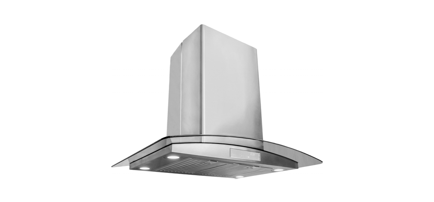
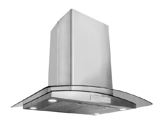
COSMO Island Mount Range HoodUser Manual
This manual is made with 100 % recycled paper.Electronic version of this manual is available at: www.cosmoappliances.com
Thank you for your purchase. We know that you have many brands and products to choose from and we are honored to know that you have decided to take one of our products into your home and hope that you enjoy it.
Our appliances are designed according to the strictest safety and performance standard for the North American market. We follow the most advanced manufacturing philosophy. Each appliance leaves the factory after thorough quality inspection and testing. Our distributors and our service partners are ready to answer any questions you may have regarding how to install, use and care for your range hood.
We hope that this manual will help you learn to use the product in the safest and most effective manner and care for it so that it may give you the highest satisfaction in cooking for years to come. If you have any questions or concerns, please contact the dealer from whom you purchased it, or contact our Customer Support at 1-888-784-3108.
The manual also includes directions for the professional installer that will install the product in your home. We recommend using trained personnel for professional installation.
Please keep this manual for future use
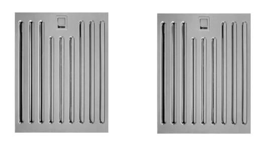
STAINLESS STEEL BAFFLE FILTERS
About Your New Filters
Stainless Steel Baffle Filters do not need linings or mesh inside of the filters and are completely constructed out of stainless steel. The stainless steel construction allows them to be used again after being cleaned or going through the dishwasher.
How do Baffle Filters Work?
They function by forcing the grease filled air to quickly and continuously change direction as it passes through the filter. The grease is unable to change direction as fast as the air carrying them, they end up getting caught on the metal blades and then trapped into the filter tray. These filters are both efficient and require less maintenance.
IMPORTANT SAFETY INSTRUCTIONS
Read all instructions before using this appliance.Save these instructions for future referencesApproved for residential appliancesFor residential use onlyIMPORTANT SAFETY INSTRUCTIONS
CAUTION
- FOR GENERAL VENTILATING USE ONLY. DO NOT USE TO EXHAUST HAZARDOUS OR EXPLOSIVE MATERIALS OR VAPORS.
- To reduce risk of fire and to properly exhaust air, do not vent exhaust air into spaces within walls, ceilings, attics, crawl spaces, or garages.
WARNING : TO REDUCE THE RISK OF FIRE, USE ONLY METAL DUCT WORK. Install this hood in accordance with all requirements specified.
WARNING : TO REDUCE THE RISK OF FIRE, ELECTRIC SHOCK, OR INJURY TO PERSONS, OBSERVE THE FOLLOWING:
A. Use this unit only in the manner intended by the manufacturer. If you have questions, contact the manufacturer
B. Before servicing or cleaning the unit, switch power off at service panel and lock service panel disconnecting means to prevent power from being switched on accidentally. When the service disconnecting means cannot be locked, securely fasten a prominent warning device, such as a tag, to the service panel.
C. Installation Work and Electrical Wiring Must Be Done By Qualified Person(s) In Accordance With all Aplicable Codes & Standards, Including Fire-rated Construction.
D. Sufficient air is needed for proper combustion and exhausting of gases through the flue (Chimney) of fuel burning equipment to prevent back- drafting. Follolow the heating equipment manufacturers guideline and safety standards such as those published by the National Fire Protection Association (NFPA), the American Society for Heating, Refrigeration and Air Conditioning Engineers (ASHRAE), and the local code authorities.
E. When cutting or drilling into wall or ceiling, do not damage electrical wiring and other hidden utilities.
F. Ducted systems must always be vented to the outdoors.
WARNING: To Reduce The Risk Of Fire Or Electric Shock, Do Not Use This Hood With Any External Solid State Speed Control Device.
GROUNDING INSTRUCTIONS
This appliance must be grounded. In the event of an electrical short circuit, grounding reduces the risk of electric shock by providing an escape wire for the electric current. This appliance is equipped with a cord having a grounding wire with a grounding plug. The plug must be plugged into an outlet that is properly installed and grounded.
WARNING – IMPROPER GROUNDING CAN RESULT IN A RISK OF ELECTRIC SHOCK.
Consult a qualified electrician if the grounding instructions are not completely understood, or if doubt exists as to whether the appliance is properly grounded.Do not use an extension cord. If the power supply cord is too short, have a qualified electrician install an outlet near the appliance.
RANGE TOP GREASE FIRE, OBSERVE THE FOLLOWING:
A. SMOTHER FLAMES with a close – fitting lid, cookie sheet, or other metal tray, then turn off the gas burner or the electric element. BE CAREFUL TOPREVENT BURNS. If the flames do not go out immediately, EVACUATE AND CALL THE FIRE DEPARTMENT.
B. NEVER PICK UP A FLAMING PAN – you may be DO NOT USE WATER, including wet dishcloths or towels – a violent steam explosion will result.
Always leave safety grills and filters in place.Without these components, operating blowers could catch onto hair, fingers and loose clothing.
The manufacturer declines all responsibility in the event of failure to observe the instructions given here for installation, maintenance and suitable use of the product. The manufacturer further declines all responsability for injury due to negligence and the warranty of the unit automatically expires due to improper maintenance.
WARNING : Unplug or disconnect the appliance from the power supply before servicing.
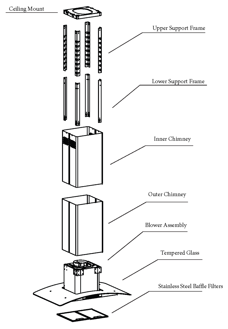
PARTS DIAGRAM
668ICS 750 / 900MAIN PARTS
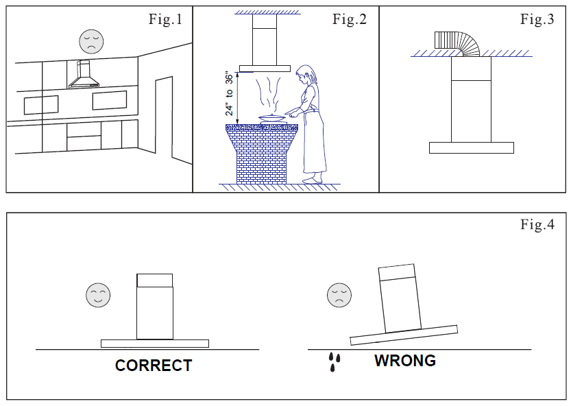
INSTALLATION REQUIREMENTS
- Do not install the range hood where there are many open doors or windows. This will cause reduced performance. (Fig. 1)
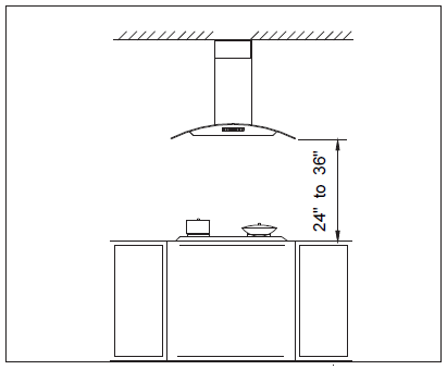
- Install the range hood right above the cooktop. The optimal distance between the cooktop and lower edge of the range hood is 24” to 36”. (Fig. 2). Install at the height appropriate to your ceiling. Make sure the chimney can still reach the ceiling. If your ceiling or preference requires installation to be a few inches higher or lower than 24-36″ you may do so without major loss of performance.
- In order to get optimal performance, do not over extend the exhaust pipe and avoid unnecessary bending. (Fig. 3)
- The air outlet must be connected to chimney flues or combustion gas ducts. Under no circumstances should the air outlet be connected to ventilation ducts for rooms in which fuel-burning appliances are installed.
INSTALLATION PROCEDURES
CAUTION: HOOD MAY HAVE VERY SHARP EDGES; PLEASE WEAR PROTECTIVE GLOVES WHENEVER IT IS NECESSARY TO REMOVE ANY PARTS FOR INSTALLING, CLEANING OR SERVICING.
Step 1:
This Island Range Hood has an adjustable height. Measure from the ceiling to a height of 24” to 36” above your cooktop. Install at a height appropriate to your ceiling. Make sure the chimney can still reach the ceiling. If your ceiling or preference requires installation to be a few inches higher or lower than 24-36″ you may do so without major loss of performance. Write down this measurement, this is the height (how tall) you will need to adjust the Island Range Hood.
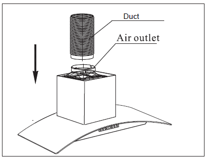
Step 2:
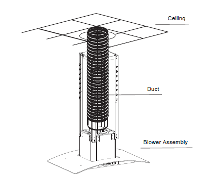
Remove the Island Range Hood from the carton and gently place on a flat workspace. Connect the Duct into the air outlet using HVAC foil tape.
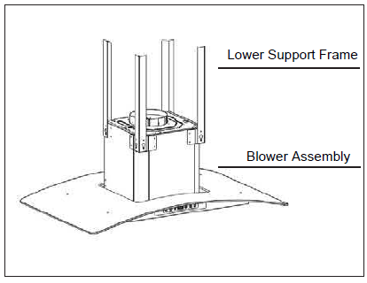
Step 3:
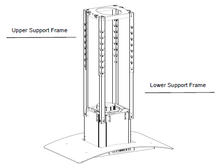
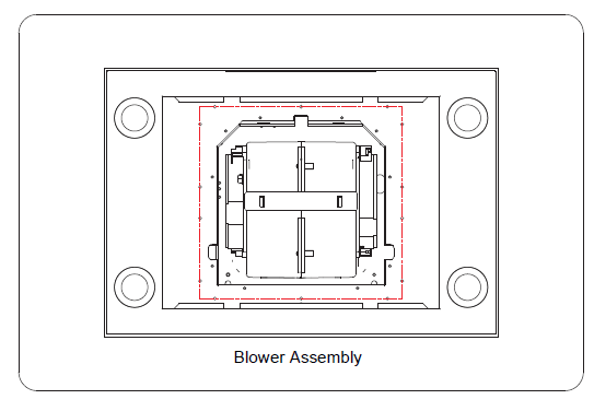
Align the 4 pieces of the Lower Support Frame to the holes on the Blower Assembly. Screw into place with the included screws. Set aside the combined Lower Support Frame and Blower Assembly.
Step 4:
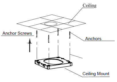
Using the Ceiling Mount as a guide drill 4 holes (8mm or 5/16 drill bit) into the ceiling area where you will be mounting your range hood. Fill the holes with the provided anchors. Screw the Ceiling Mount securely into place.Note: In some cases the Ceiling Mount may already be attached to the Upper Support Frame
Step 5:
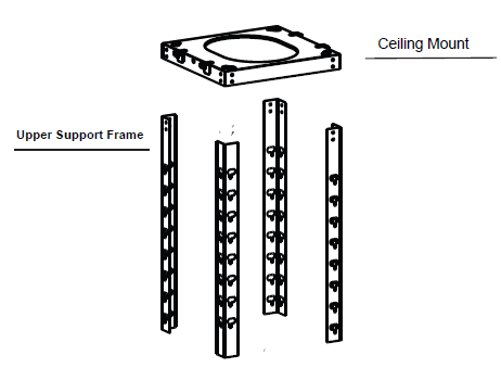
Align the 4 pieces of the Upper Support Frame to the holes on the Ceiling Mount. Securely screw into place with the included screws.
Step 6:
Slide the Lower Support Frame into the Upper Support Frame. Adjust the height according to what you measured in Step 1.Align the holes to the desired height, screw the 4 pieces of the Lower Support Frame to the 4 pieces of the Upper Support Frame together.
Step 7:
Extend Duct from the Blower Assembly to the ceiling through the Ceiling Mount and Connect to existing duct work.
Step 8:
Take the back piece of the Inner Chimney, align and securely screw into the sides of the Ceiling mount.Now take the front piece of the Inner Chimney, align and securely screw into the sides of the Ceiling mount.Now connect the Back of the Inner Chimney and the Front of the Inner Chimney together on each side (where they meet).

Step 9:
Take the Back of the Outer Chimney and the Front of the Outer Chimney and connect them together as shown in the picture. Now screw the Back of the Outer Chimney and the Front of the Outer Chimney together on each side (where they meet).
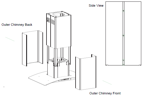
Step 10:
Remove Filters to access the bottom of the Blower Assembly. From the bottom of the Island Range Hood, secure the Outer Chimney (Back and Front Pieces) by screwing them into the Blower Assembly.
Step 11:
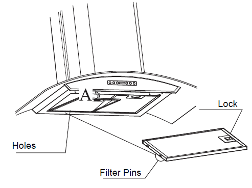
Reinstall the Baffle Filters. Align the filter pins with the holes under the range hood. Gently pull on filter lock. Put the filter in place and release lock.
RE CIRCULATING CHARCOAL FILTERS
Skip this page if you are installing a Ducted Range Hood.Charcoal Filters are only included with Ductless Models
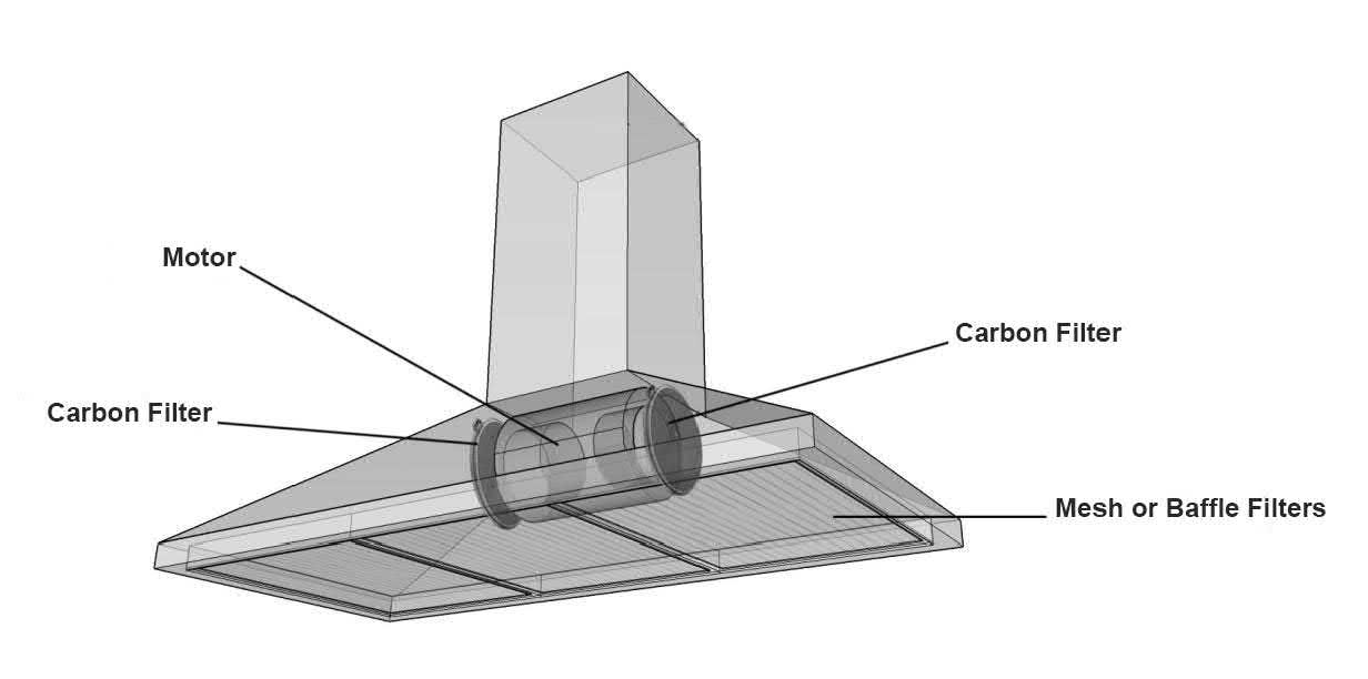
Installing Recirculating Filters (For Ductless Model Only)
- Remove the Baffle Filters
- Locate the Motor
- Place a Carbon Filter on one side of the motor and align with the clips.
- Twist and Lock into Place.
- Repeat steps 2-4 for the other side of the motor.
- Place the Baffle Filters back into place.Skip this page if you are installing a Ducted Range Hood.Charcoal Filters are only included with Ductless Models
- Chimney Vent Holes located on the sides of the chimney must be exposed to let the filtered air recirculate.
OPERATING INSTRUCTIONS

A. Timer ButtonWhen unit is turned on press to increase auto-shutoff timer up to 59 minutes.
B. Light Button.Press to turn lights on / off
C. Fan Speed ButtonWhen unit is turned on press to change fan speed.
D. Power ButtonPress to turn unit on / off.
How to Set your Time
The clock on this Range Hood is set to military time. It cannot be set to a 12-hour format.
- Press Power Button – The display panel will illuminate.
- Hold Timer Button until unit beeps – The time will start flashing.
- While the time is flashing use the Light Button to set the hours. Use the Fan Speed Button to set the minutes.
- After ten seconds of not pressing anything, the settings will save.
MAINTENANCE
CAUTION: NEVER PUT YOUR HAND INSIDE OF THE UNIT WHILE ITS OPERATING. FORTHE BEST PERFORMANCE CLEAN YOUR RANGE HOOD REGULARLY.
CLEANING
- Use only mild soap or cleaning solutions to clean the range hoods outer surface. Dry surfaces using a soft cloth.
- Stainless Steel cleaner may be used on the external surface.
- Cleaning the Baffle Filters: For daily cleaning, use hot, soapy water and a soft cloth. Wipe dry and finish with a damp micro-fiber cloth. Baffle filters can also be cleaned in the dishwasher.
- Clean the Range Hood assembly once every 6 months.
- DO NOT clean the motor or electrical components with water or any other liquid
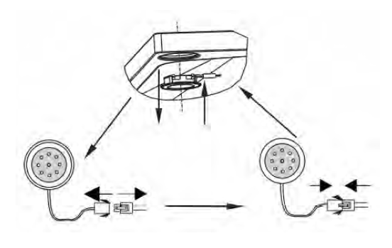
REPLACING LIGHT BULBS
CAUTION: LAMP UNIT MAY BE HOT! WAIT UNTIL THE UNIT IS COOL. BEFORE ATTEMPTING TO REPLACE THE LED LAMPS MAKE SURE THE UNIT IS POWERED OFF AND UNPLUGGED.
Note: Individual LED bulbs cannot be replaced, only entire LED lamps.
- Remove the baffle filters
- Find the wire connection of the lamp inside the unit and unplug.
- Remove old LED lamp by pushing it out of its hole from the inside.
- Plug in new LED lamp.
- Reinstall the baffle filters.
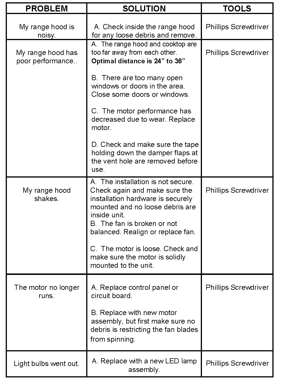
TROUBLESHOOTING
CAUTION: ALWAYS UNPLUG UNIT FROM POWER BEFORE SERVICING
WARRANTY AND SERVICE
Information
Need Help finding the Model Number or Serial Number?
The model number and serial number can be found on the box of each unit.
Range Hoods – The Serial Number can be found inside of the unit located on the motor housing.Ranges – The Serial Number can be found on the back of the unit towards the bottom.Ovens – The Serial Number can be found by opening the door and looking towards the bottom.Dishwasher — The Serial Number is found on the inside of the door jamb.Refrigerator — The Serial Number is found on the rear of the unit.Cooktops — The Serial Number is found underneath the unit.Faucets – Enter the order number located on your receipt in the Serial Number field.Sous Vide Machines – Enter the order number located on your receipt in the Serial Number field.
Customer Support
Give us a call at: 1-888-784-3108Monday Through Friday: 9:00 AM PST to 5:00 PM PSTEmail us at:
Notice
Please verify that all of the information above is correct. Entering an incorrect Serial # or Product Model # will not register your Warranty.
Warranty Terms
ATTACH YOUR RECEIPT HERE. PROOF OF PURCHASE IS REQUIREDTO OBTAIN WARRANTY SERVICE.Please have the following information available when you call theCustomer Service Center:
- Name, address and telephone number
- Model number and serial number
- A clear, detailed description of the problem
- Proof of purchase including dealer or retailer name and address
FIVE YEAR LIMITED WARRANTY
This unit comes with 5 Year Manufacturer’s Part Warranty. Within 5 years after date of receiving the product, Cosmo will replace any functional parts that are defective. The customer must contact Cosmo and provide a description of the defective part, including digital pictures if requested, along with original proof of purchase. Defective components must be returned to Cosmo shipping prepaid. After the 1st year, shipping costs of replacement parts will also be prepaid by customer.Functional parts are those components/parts that are crit- ical to the performance of the product’s essential function.
Non-functional parts are those that are a cosmetic feature of the product such as knobs, grates, other metal bodies/surfac- es, etc. In the event of product replacement, your appliance will be warranted for the remaining term of the original unit’s warranty period.
[xyz-ips snippet=”download-snippet”]