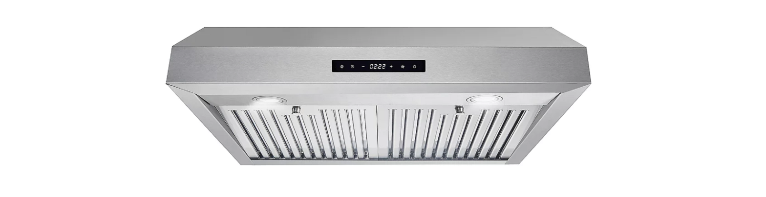
COSMO Under Cabinet Range Hood User Manual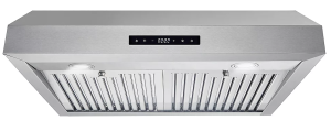
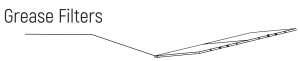
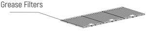
STAINLESS STEEL BAFFLE FILTER
About Your New FiltersStainless Steel Baffle Filters do not need linings or mesh inside of the filters and are completely constructed out of stainless steel. The stainless steel construction allows them to be used again after being cleaned or going through the dishwasher.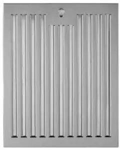
How do Baffle Filters Work?They function by forcing the grease filled air to quickly and continuously change direction as it passes through the filter. The grease is unable to change direction as fast as the air carrying them, they end up getting caught on the metal blades and then trapped into the filter tray. These filters are both efficient and require less maintenance.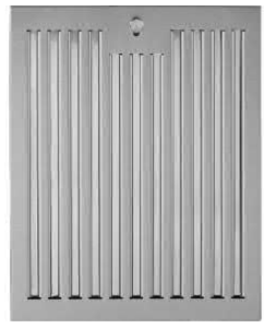
IMPORTANT SAFETY INSTRUCTIONS
Read all instructions before using this appliance. Save these instructions for future references Approved for residential appliancesFor residential use only
![]() CAUTIONFOR GENERAL VENTILATING USE ONLY. DO NOT USE TO EXHAUST HAZARDOUS OR EXPLOSIVE MATERIALS OR VAPORS.
CAUTIONFOR GENERAL VENTILATING USE ONLY. DO NOT USE TO EXHAUST HAZARDOUS OR EXPLOSIVE MATERIALS OR VAPORS.
![]() CAUTIONThis product is designed for indoor residential use only.
CAUTIONThis product is designed for indoor residential use only.
![]() CAUTIONTo reduce risk of fire and to properly exhaust air, do not vent exhaust air into spaces within walls, ceilings, attics, crawl spaces, or garages.
CAUTIONTo reduce risk of fire and to properly exhaust air, do not vent exhaust air into spaces within walls, ceilings, attics, crawl spaces, or garages.
![]() WARNINGTO REDUCE THE RISK OF FIRE, USE ONLY METAL DUCT WORK. Install this hood in accordance with all requirements specified.
WARNINGTO REDUCE THE RISK OF FIRE, USE ONLY METAL DUCT WORK. Install this hood in accordance with all requirements specified.
![]() WARNINGTO REDUCE THE RISK OF FIRE, ELECTRIC SHOCK OR INJURY TO PERSONS OBSERVE THE FOLLOWING:
WARNINGTO REDUCE THE RISK OF FIRE, ELECTRIC SHOCK OR INJURY TO PERSONS OBSERVE THE FOLLOWING:
A. Use this unit only in the manner intended by the manufacturer. If you have questions, contact the manufacturer,B. Before servicing or cleaning the unit, switch power off at service panel and lock service panel disconnecting means power from being switched on accidentally. When the service disconnecting cannot be locked, securely fasten a prominent warning device, tag, to the service panel.C. Installation Work and Electrical Wiring Must Be Done By Qualified Person(s) In Accordance With all Aplicable Codes & Standards, Including Fire-rated Construction.D. Sufficient air is needed for proper combustion and exhausting of gases through the flue (Chimney) of fuel burning equipment to prevent back- drafting.Follolow the heating equipment manufacturers guideline and safety standards such as those published by the National Fire Protection Association (NFPA), the American Society for Heating, Refrigeration and Air Conditioning Engineers (ASHRAE), and the local code authorities.E. When cutting or drilling into wall or ceiling, do not damage electrical wiring and other hidden utilities.F. Ducted systems must always be vented to the outdoors.
![]() WARNING
WARNING
To Reduce The Risk of Fire or Electric Shock Do not use This Hood with any external solid state Speed control Device.
![]() WARNING
WARNING
GROUNDING INSTRUCTIONS
This appliance must be grounded. In the event of an electrical short circuit, grounding reduces the risk of electric shock by providing an escape wire for the electric current. This appliance is equipped with a cord having a grounding wire with a grounding plug. The plug must be plugged into an outlet that is properly installed and grounded.
WARNING – IMPROPER GROUNDING CAN RESULT IN A RISK OF ELECTRIC SHOCK.
Consult a qualified electrician if the grounding instructions are not completely understood, or if doubt exists as to whether the appliance is properly grounded. Do not use an extension cord. If the power supply cord is too short, have a qualified electrician install an outlet near the appliance.
![]() WARNING
WARNING
TO REDUCE THE RISK OF INJURY TO PERSONS, IN THE EVENT OF A RANGE TOP GREASE FIRE, OBSERVE THE FOLLOWING:
A. SMOTHER FLAMES with a close – fitting lid, cookie sheet, or other metal tray, then turn off the gas burner or the electric element. BE CAREFUL TO PREVENT BURNS. If the flames do not go out immediately, EVACUATE AND CALL THE FIRE DEPARTMENT.
B. NEVER PICK UP A FLAMING PAN – you may be burned. DO NOT USE WATER including wet dishcloths or towels – a violent steam explosion will result.
Always leave safety grills and filters in place. Without these components, operating blowers could catch onto hair, fingers and loose clothing. The manufacturer declines all responsibility in the event of failure to observe the instructions given here for installation, maintenance and suitable use of the product. The manufacturer further declines all responsibility for injury due to negligence and the warranty of the unit automatically expires due to improper maintenance.
![]() WARNING
WARNING
Unplug or Disconnect the appliance from the power supply before servicing.
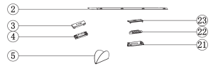
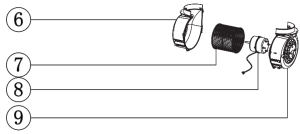
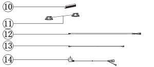
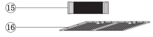
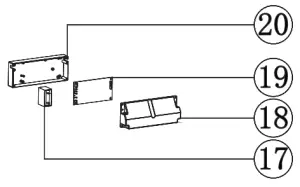
PARTS DIAGRAM
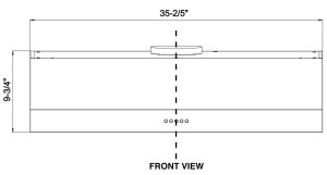
PARTS INCLUDED
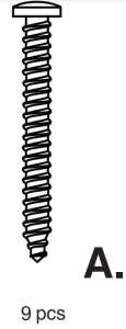
- A. 9 pcs – 4×30 screws

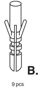
- B. 9 pcs – Wall Anchors
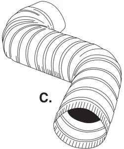
- C. 6″ Round Aluminum Duct
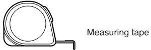
PARTS REQUIRED


PRE-INSTALLATION REQUIREMENTS
- Do not install the Range Hood where there are many dorrs or win-dows in order to avoid effecting the exhaust efficiency caused by air convection.
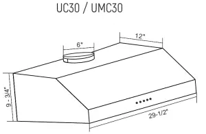
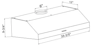
- Install the Range hood directly above the cooking surface. The recommended distance between the cooking surface and the bottom of the range is minimum 24″ and Maximum 30″.
- In order to get the optimum performance, do not extend the vent pipe too far , adjust the vent pipe, and make sure the hood is level and vertical.
- The air outlet must not be connected to chimney flues or combustion gas ducts. The air outlet must not be connected to ventilation ducts for rooms in which fuel-burning appliances are installed.
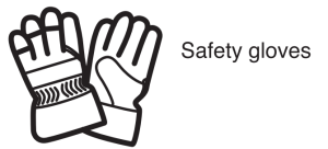
SAFETY WARNING
HOOD MAY HAVE SHARP EDGES; PLEASE WEAR PROTECTIVE GLOVES /F /TS NECESSARY TO REMOVE ANY PARTS FOR INSTALLING, CLEAN/NG, OR SERVICING.
INSTALLATION INSTRUCTION
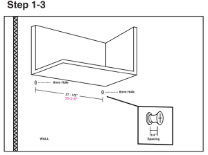
- 1.Drill two 8mm holes in position for Wall Anchor (Part B) placement.
- Tap Wall anchors securely into each of the drilled holes.
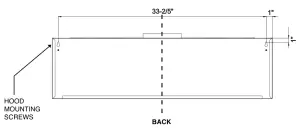
- After Wall anchors have been tapped in place, Insert 4×30 screws, but leave 1/4of the screw sticking out of the wall. (This will give your Range Hood something to hang onto).
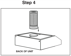
- Take the hood unit along with the 6Round Aluminum duct (Part D). Secure the round alumi-num duct to the vent hole at the top of the hood unit using HVAC Aluminum foil tape.If mounting to a cabinet, skip step 5 and proceed with steps 6 11.
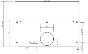
- If mounting to the wall only, drill a 6-1/4 round hole on the back wall above the hood, OR into the ceiling directly above the hood. 5a. Remove baffle filters from underneath the hood and set them aside. 5b. Lift the hood and hang the hood unit on the back wall using the screws drilled in Step 3. Once the hood is securely hung on the wall, tighten the screws from the interior of the hood. 5c. Pull round aluminum duct through the newly drilled hole in the wall. Plug unit into power outlet. Reinstall baffle filters.
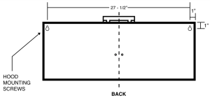
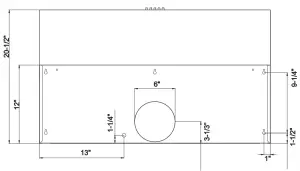
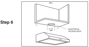
- Drill a 6 – 1/4Round Hole into the bottom of the cabinet. Drill a 1 – 1/2hole into the bottom of the cabinet for the Electrical Access hole. See Page 5 for hole location according to the diagram (Top View). 6a. Pull the round duct & power cord through the bottom of the new cabinet holes.
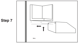
- Lift the hood and hang the hood unit on the back wall using the screws drilled in Step 3.
- Once the Hood is hung to the back wall, Remove the baffle filters from underneath the hood.
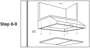
- Drill each of the five pieces of 4×30 screws (Part C) into the bottom of the cabinet using the five screw holes at the top of the hood.
- Once the hood is secured into the cabinet, tighten the wood screws located in the back of the hood. Install Baffle filters back into place. Make sure hood is secure by pressing on it. Plug unit into power outlet.
 If mounting to a cabinet, skip step 5 and proceed with steps 6 11.
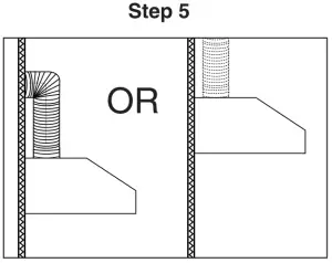
IMPORTANT SAFETY INSTRUCTION
- Please always supervise children and any other individuals that should be monitored while using this appliance.
- Do not connect the air outlet to chimney fuels or combustion gas ducts.
- Do not leave unattended open flames under this hood.
- In case of any damage to power cable, replace the broken cable with a new one by a qualified professional.
- Clean the hood as instructed in this manual. If the hood is not cleaned or cleaned improperly, it may cause fire, or the range hood may function incorrectly.
- The LED lamp should be replaced by a qualified professional. Always use a 2W LED light or less
- Do not wash the control switch with water, as it will cause elec-trical issues for the range hood.
- Do not pull the plug from the power supply with wet hands to avoid electrical shock.
- Disconnect the hood from the power supply if the appliance will not be used for an extended period of time.
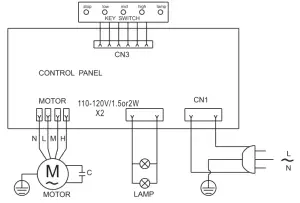
OPERTATING INSTRUCTION
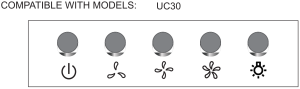
Push Button ControlsHow to use the Push Button:
![]() Press to select on/off.
Press to select on/off.
![]() Press to select the low speed.
Press to select the low speed.
![]() Press to select the medium speed.
Press to select the medium speed.
![]() Press to select the high speed.
Press to select the high speed.
![]() Press to turn on /off the light.
Press to turn on /off the light.
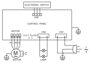
Soft Touch ControlsCOMPATIBLE WITH MODELS: UMC30
A. Light. Press to turn light on / off.B. Timer ButtonC. Minus Button (Fan Speed)D. Plus Button (Fan Speed)E. Fan Power Button (Starts Max Fan Speed)F. Power Button. Press to turn unit On/OffNote: When Fan is ON + or button will go to Min or Max Settings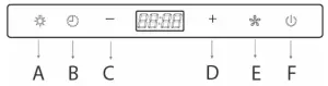
Setting the ClockClock is in Military Time and cannot be changed.
- Hold Timer Button for 3 Seconds Use Light Button (A) to set Minutes Use Fan Speed Button (E) to set Hours
- Once time is set, Press Timer button to complete.
- After setting the time, leave the unit alone for 5 seconds for the changes to save.
Setting the Timer
- Turn fan on and set to desired fan speed.
- Press the Timer Button (B). Continue tapping the Timer Button (B) to set the time duration before the fan should automatically turn off.
- After setting the timer, leave the unit alone for 5 seconds for the changes to save and the timer will start counting down.
MAINTENANCE
CAUTION: Never put your hand inside the unit while it is operating. For the best performance clean your unit frequently.
CLEANING:
- Use only mild soap or cleaning solutions to clean the range hoods outer surface. Dry surfaces using a soft cloth.
- Stainless Steel cleaner may be used on the external surface.
- Cleaning the Baffle Filters: For daily cleaning, use hot, soapy water and a soft cloth. Wipe dry and finish with a damp micro-fiber cloth. Baffle filters can also be cleaned in the dishwasher.
- Clean the Range Hood assembly once every 6 months.
- DO NOT clean motor or electrical components with water or any other liquid.
REPLACING LIGHT BULBS
CAUTION: LED LAMP UNIT IS HOT! WAIT BEFORE ATTEMPTING BEFORE ATTEMPTING TO REPLACE LED LAMPS. PLEASE BE SURE THE UNIT IS POWERED OFF & UNPLUGGED.
NOTE: INDIVIDUAL LED BULBS CANNOT BE REPLACED. ONLY LED LAMPS.
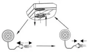
- Remove the baffle filters.
- Find the wire connection of the lamp and unplug.
- Remove old LED lamp.
- Plug in new LED lamp.
- Reinstall the baffle filters.
TROUBLESHOOTING
CAUTION: ALWAYS UNPLUG UNIT FROM POWER BEFORE SERVICING
|
PROBLEM |
SOLUTION |
TOOLS |
|
My range hood is noisy |
A. Check inside the range hood for any loose debris and remove. If your range hood is still noisy after checking, please call 1-888-784-3108. |
Phillips Screwdriver |
|
My range hood has poor performance |
A. The range hood and cooktop are too far away from each other. Optimal distance is 24″ to 36″ B. There are too many open windows or doors in the area. Close some doors or windows. C. The motor performance has decreased due to wear. Replace motor. D. Check and make sure the tape holding down the damper flaps at the vent hole are removed before use.E. The filters are clogged and need to be cleaned. |
Phillips Screwdriver |
|
My range hood shakes |
A. The installation is not secure. Check again and make sure the installation hardware is securely mounted. B. The fan is broken or not balanced. Re-align or replace fan. C. The motor is loose. Check and make sure the motor is solidly mounted to the unit. D. Baffle filter is loose and is not installed correctly. Read page 12 for installation instructions. |
Phillips Screwdriver |
|
Range Hood does not turn on |
A. Make sure that range hood is plugged into powered outlet. Test outlet with other device if not working. B. Remove baffle filters, reach inside behind the control panel and locate the wire with clip. Make sure control panel is securely plugged in. |
Phillips Screwdriver |
|
Light bulbs went out |
A. Replace with a new LED lamp assembly.B. Remove baffle filters, reach inside behind the control panel and locate the wire with clip behind the light housing. Make sure the light is securely plugged in. |
Phillips Screwdriver |
IF YOU HAVE TRIED ALL SOLUTIONS AND STILL EXPERIENCE ISSUES, PLEASE CALL SUPPORT: 1-888-784-3108
TECHNICALE INFORMATION
UC 30/UMC 30UC 36/UMC 36
|
NO. |
Parts name | Qty/hood |
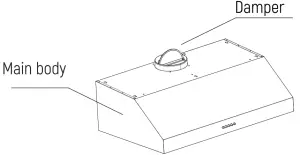
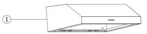
| 1 | Main Body |
1 |
|
2 |
Light SS panel | 1 |
| 3 | Upper Plastic cover |
1 |
|
4 |
Bottom Plastic cover | 1 |
| 5 | Non-return Valves |
2 |
|
6 |
Left plastic cover | 1 |
| 7 | Plastic fan |
1 |
|
8 |
Motor | 1 |
| 9 | Right plastic cover |
1 |
|
10 |
Wire clip | 1 |
| 11 | LED |
2 |
|
12 |
Light connect wire | 1 |
| 13 | Push button connect wire |
1 |
|
14 |
American 3pins cable | 1 |
| 15 | 2m aluminum pipe |
1 |
|
16 |
Baffle filters | 2/3 |
| 17 | 15uF Capacitor |
1 |
|
18 |
PCB box cover | 1 |
| 19 | PCB for push button |
1 |
|
20 |
PCB box bottom cover | 1 |
| 21 | Push button cover |
1 |
|
22 |
Push button | 1 |
| 23 | Push button bottom cover |
1 |
IMPORTANT
Do Not Return This Product To The Store If you have a problem with this product, please contact Cosmo Customer Support at +1(888)784-3108DATED PROOF OF PURCHASE, MODEL ft, AND SERIAL # REQUIRED FOR WARRANTY SERVICE
Correct Disposal of this product:This marking indicates that this appliance should not be disposed with other household wastes. To prevent possible harm to the environment or human health from uncontrolled waste disposal, recycle it responsibly to promote the sustainable reuse of material resources.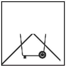
WARRANTY AND SERVICE
 report this ad
For full warranty details on this product please visit: http://www.cosmoappliances.com/warrantyTO RECEIVE WARRANTY SERVICE, YOUR PRODUCT MUST BE REGISTERED. TO REGISTER,VISIT:WWW.COSMOAPPLIANCES.COM/WARRANTYSCAN TO REGISTER
 APPLIANCE
[xyz-ips snippet=”download-snippet”]