![]() Pro-Set® LDA1000HRefrigerant Leak Detector
Pro-Set® LDA1000HRefrigerant Leak Detector
OPERATION MANUAL
GENERAL INFORMATION
Introduction
LDA1000H Overview
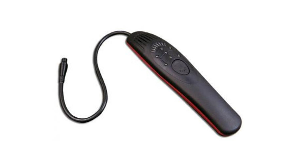
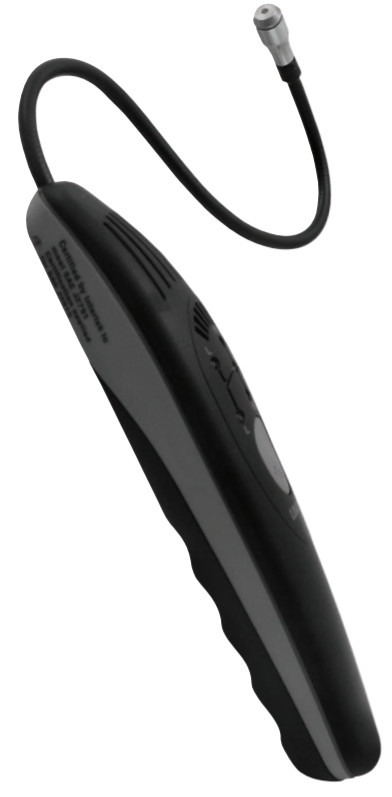
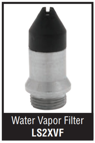
The LDA1000H is the first automotive electronic leak detector utilizing E_MOS® sensor technology. Following the guidelines of the latest SAE standard specifications for leak detectors, the LDA1000H offers the user two detection modes: one optimized for R-134a and the other for HFO-1234yf. Each mode has four sensitivity settings according to the requirements of the SAE standards.Efficient control of the power to the sensor increases the life of the batteries while ensuring that the sensor is operated at its optimum condition in every mode. Although designed with SAE standards in mind, the LDA1000H’s advanced sensor technology is sensitive to all CFC, HCFC, and HFC refrigerants as well as approved blends.The LDA1000H is housed in an ergonomically shaped high impact plastic chassis with a flexible 15″ probe for rugged automotive use. The sensor is enclosed in a metal cage designed to protect the sensor from dirt and water.The LDA1000H is shipped with the J2791 style sensor cap. This cap allows performance as indicated under J2791 and J2913, which can be removed and cleaned if the opening gets clogged with dirt. In areas where humidity is high, the patented CPS Water A vapor Filter cap is recommended to eliminate false alarms. One LS2VF water vapor filter cap is included with the LDA1000H.
FEATURES:
- Microprocessor-controlled sensor electronics utilizing a multi-channel signal detection method improves sensitivity while reducing false alarms.
- New sensor technology incorporates a proprietary pulse modulation design to increase both battery and sensor life.
- Software-managed sensor rejuvenation mode, initiated at each startup ensures the highest level of sensitivity every use, for up to 500 hours of detecting leaks of less than .1 oz per year.
- Sensitivity remains constant over the life of the sensor.
- Meets all U.S. and International standards for automotive use including SAE J2913 for HFO-1234yf, SAE J2791 for R-134a and European Standard EN14624:2012. Superior sensitivity to all CFC, HCFC, HFC, and HFO gases and blends.
- 50-hour battery life (3) “C” batteries. Auto-Off after 10 minutes. Green LED low battery indicator.
- 500 hours sensor life.
- 2-year warranty.
- Both visual and audible leak indicators.
- Patented.
LDA1000H Specifications
| Sensor: | State of the art E_MOS® technology |
| Gases: | Sensitive to CFC, HCFC, HFC, and HFO refrigerants.Sensitive to the Hydrogen trace gas in 95% N2, 5% H2 mixture. Sensitive to NH3 and HC refrigerants.CAUTION: This leak detector is not intrinsically safe. Use in well-ventilated areas. Instrument factory calibrated to meet the requirements of SAE J2791 and J2913. |
| Calibration: | While moving 3″ / sec. (75mm / sec.) at 3/8″ (9.5mm) from calibrated leak source. |
| R-134a | L = 14 g / yr. (0.5 oz / yr.) or greaterM = 7 g / yr. (0.25 oz / yr.) or greaterS = 4 g / yr. (0.15 oz / yr.) or greaterSC = 4g / yr. (0.15 oz / yr.) or greater in 500 ppm. or less by weight R-134a contaminated atmosphere. |
| HFO-1234yf | L = 14 g / yr. (0.5 oz / yr.) or greaterM = 7 g / yr. (0.25 oz / yr.) or greaterS = 7 g / yr. (0.25 oz / yr.) or greaterSC = 4g / yr. (0.15 oz / yr.) or greater in500 ppm. or less by weight HFO-1234yf contaminated atmosphere. |
| The LDA1000H gives an indication within 5 seconds when the probe is held stationary at 5mm (0.2″) from a calibrated leak source of R-134a set for 3 g / yr. per EN14624:2012. | |
| Audible Alarms: | High pitched wide tone range audible alarm in settings L, M, and S. Low pitched audible alarm in SC settings. |
| Visual Alarms: | An 8 segment bar-graph LED display shows the relative leak size. |
| OperatingTemperature: | -18 to 60˚C (0 to 140˚F) |
| Power: | Three sizes “C” alkaline batteries (NEDA/ANSI 14A) |
| Battery Life: | 50 hours minimum at 77˚F (25˚C). Battery life depends on cell chemistry and ambient conditions.Alkaline batteries provide the longest life.Cold ambient conditions decrease battery life.The LDA1000H turns itself off after 10 minutes of inactivity—START button not pressed—to further, prolong battery life. |
| Dimensions: | Instrument (L x W x H): 10″ x 2.3″ × 2″ 254mm x 59mm x 51mm |
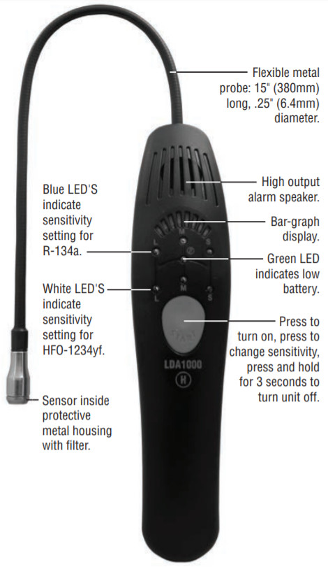
| Probe: | 15″ (380mm) long, .25″ (6.4mm) diameter |
| Weight: | 1 lb 2 oz (500 g) |
| Certifications: | Complies with European StandardEN14624:2012. SAE J2791 and J2913 |
OPERATION
Using the LDA1000H
Turning the instrument ON:Press the red START button once to turn the unit ON. The instrument initiates a sensor self-cleaning and conditioning cycle which lasts for 35 seconds. During that time, the bar graph indicator lights scan from left to right. When the audible alarm turns on the instrument is ready to use.Sensitivity settings:The LDA1000H features 8 manually selectable settings, 4 for the R-134a mode—L, M, S, and SC—indicated by blue LED’s, and 4 for the HFO-1234yf mode—L, M, S, and SC—indicated by white LEDs. The instruments start in the Large Leak (L) setting for the R-134a mode and advance clockwise with every press of the red START button.The unit will always start in the lowest sensitivity position in the R134a mode. In this mode, the instrument responds to leak rates equal to or greater than 14 g / yr (0.5 oz / yr.).The bar graph indicator shows the user how much bigger than the leak rate the detected leak is. If no indication is obtained in that setting, then press the red START button to advance the sensitivity to the 7 g / yr. (0.25 oz / yr). If no indication is obtained in this range, then press START again and go to the highest sensitivity setting of 4 g / yr (0.15 oz/yr).Pressing the START button once again puts the LDA1000H in a unique setting specially designed to be used in heavily contaminated atmospheres. This setting is identified by a lower tone of the alarm which increases in volume and frequency when the leak is detected in the contaminated atmosphere.Pressing the START button once more puts the instrument in the lowest sensitivity setting of the HFO-1234yf mode.Subsequent activation of the START button repeats the above sequence for the HFO-12134yf refrigerant.Note: The LDA1000H is sensitive to all refrigerants currently used in the automotive industry. If the vehicle being checked for leaks uses a refrigerant other than R-134a or HFO-1234yf, use the R-134a mode of the LDA1000H.Turning the instrument OFF:At any time during operation, press and hold down the red START button until the LED display turns OFF. This indicates that the unit has been shut down.Low battery indicator :![]() When the batteries reach approximately 10% of capacity, the green LED next to the symbol (
When the batteries reach approximately 10% of capacity, the green LED next to the symbol (![]() ) will turn off.Windy conditions:Locating leaks under windy conditions may severely impede the leak-searching process. Even very large leaks may be difficult to locate as the escaping gas is quickly dissipated into the atmosphere. If necessary, fabricate a gas trap using aluminum foil around joints or fittings or otherwise shield thesearch area from the wind.Leak verification:If a suspected leak is indicated, verify several times by moving the sensor away from the leak area, resetting the unit, and then back to the suspected leak. If the instrument indicates a leak three consecutive times, then you have found a leak.
) will turn off.Windy conditions:Locating leaks under windy conditions may severely impede the leak-searching process. Even very large leaks may be difficult to locate as the escaping gas is quickly dissipated into the atmosphere. If necessary, fabricate a gas trap using aluminum foil around joints or fittings or otherwise shield thesearch area from the wind.Leak verification:If a suspected leak is indicated, verify several times by moving the sensor away from the leak area, resetting the unit, and then back to the suspected leak. If the instrument indicates a leak three consecutive times, then you have found a leak.
Searching For Leaks
The LDA1000H features automatic tuning out of background contamination and needs only to be turned on to begin leak searching. All necessary sensitivity and calibration settings are selected by the unit’s advanced control software providing optimal leak finding performance at any setting.It is recommended to follow the guidelines stated in SAE J1628 latest release. The basic steps are outlined below. Always leak test with the engine OFF.
- With the system, OFF, pressurize it by charging with enough refrigerant to attain a pressure of at least 350 KPa (50 PSIG).
- Take care not to plug the sensor housing cap by dragging it over dirty or wet surfaces. If the area is particularly dirty, or condensate (moisture) is present, it should be wiped off with a dry shop towel. Consult the list of substances to which the LDA1000H may react on pages 8 & 9. If any of these substances are present, clean with a dry cloth.
- Visually trace the entire refrigerant system and look for signs of air conditioning lubricant leakage, damage, and corrosion on all lines, hoses, and components. Each questionable area should be carefully checked with the detector: controls, service ports with caps in place, brazed or welded areas, and areas around attachment points and hold-down on lines and components. If looking for an apparently larger leak, check first at 7 g / yr or 14 g / yr settings.
- Turn on the LDA1000H and allow it to warm up outside the area to be searched. Based on an estimate of the system’s leak rate, set the LDA1000H to the appropriate refrigerant and sensitivity setting. The LDA1000H provides sensitivity settings of 14 g / yr (0.5 oz / yr), 7 g / yr (0.25 oz / yr) and 4 g / yr (0.15 oz / yr) corresponding to the L, M and S marked LEDs. If the detector alarms when the area to be searched is approached, ventilate the area to eliminate any accumulation of refrigerant which may obscure the smaller leaks.
- Always follow the refrigerant system around in a continuous path so that no areas of potential leaks are missed. If a leak is found, always continue to test the remainder of the system.
- Recheck service valves with caps removed. Blow shop air over the service valves to clear immediate area, and then check with a detector on a 7 g / yr set.
- At each area checked, the probe should be moved around the location at a rate of no more than 3 in / sec. (75mm / sec.), and no more than 3/8″ (9.5mm) from the surface, completely encircling each test position (switch, sensor, refrigerant tubing connection, etc).Slower and closer movement of the probe greatly improves the likelihood of finding a leak. However, detectors made to meet the SAE J2791 and J2913 standards are based on air sampling from a 3/8″ (9.5mm) distance. A retest is, therefore, advisable when a leak appears to be found at the most sensitive settings, particularly if the probe was in a static position on a joint, or making physical contact with a joint, as it was moving. Go over that suspected location moving the probe and taking care to maintain the small gap (3/8″ or 9.5mm) to confirm that the leak is of repairable size. Use the 7 g / yr (0.25 oz/yr) setting after finding an apparent leak with the 4 g / yr (0.15 oz/yr) setting may also be helpful.
- When testing for a leak at the compressor, move the probe along the compressor body joints, along the pressure relief valve, any switches, and the all-around compressor shaft seal area. Shaft seals normally leak during compressor operation so it may be very difficult to ascertain if a leak exists because the testing with an electronic leak detector is performed with the system off. However, any indication from the LDA1000H in a setting below the 14 g / yr. (0.5 oz / yr.) maybe an indication that a significant leak has been found, especially if no other leaks have been located.
- Following any service to the refrigerant system, and any other service that disturbs the refrigerant system, a leak test of the repair and of the service ports of the refrigerant system should be done.
Note: This detector may alarm if in a area of heavy contamination. In such situations, use the SC setting of either the R-134a or the HFO-1234yf modes. If possible, it is always advisable to clear heavy contamination of refrigerant using shop air prior to searching for leaks.
 Note: Included with the LDA1000H is a patented water vapor filter cap which should be used when searching for leaks in areas of high humidity.
Chemical Sensitivity Chart for R-134a
|
Automotive Chemical |
Sensitivity |
Clears in < 30 seconds |
| Ford spot and stain remover. | Yes | Yes |
| Ford rust penetrant and inhibitor | Yes | Yes |
| Ford gasket and trim adhesive | Yes | Yes |
| Ford brake parts cleaner | Yes | Yes |
| Ford clear silicone rubber uncured | Yes | Yes |
| Motorcraft G-05 anti-freeze coolant heated to 160°F | Yes | Yes |
| Ford pumice/lotion hand cleaner | Yes | Yes |
| Motorcraft DOT3 brake fluid | No |
– |
| Ford spray carburetor tune-up cleaner | Yes | Yes |
| Ford silicone lubricant | No |
– |
| Windshield washer solvent (methanol base) | Yes | Yes |
| Permatex natural blue cleaner and degreaser | Yes | Yes |
| Gunk liquid wrench | Yes | Yes |
| Dextron automatic transmission fluid heated to 160°F | No |
– |
| Mineral engine oil heated to 160°F | No | – |
![]() CAUTION: This leak detector is sensitive to some common automotive cleaners and solvents on or near refrigerant lines. Wipe away dirt and potential false-triggeringchemicals using a dry shop towel or shop air.
CAUTION: This leak detector is sensitive to some common automotive cleaners and solvents on or near refrigerant lines. Wipe away dirt and potential false-triggeringchemicals using a dry shop towel or shop air.
Chemical Sensitivity Chart for HF0-1234yf
| Automotive Chemical | Sensitivity | 30 seconds |
| Ford spot and stain remover. | Yes | Yes |
| Ford rust penetrant and inhibitor | Yes | Yes |
| Ford gasket and trim adhesive | Yes | Yes |
| Ford brake parts cleaner | Yes | Yes |
| Ford clear silicone rubber uncured | No | — |
| Motorcraft G-05 anti-freeze coolant heated to 160T | Yes | Yes |
| Ford pumice/lotion hand cleaner | Yes | Yes |
| Motorcraft DOT3 brake fluid | No | — |
| Ford spray carburetor tune-up cleaner | Yes | Yes |
| Ford silicone lubricant | No | — |
| Windshield washer solvent (methanol base) | Yes | Yes |
| Permatex natural blue cleaner and degreaser | Yes | Yes |
| Gunk liquid wrench | Yes | Yes |
| Dextron automatic transmission fluid heated to 160T | No | — |
| Mineral engine oil heated to 160`f | No | — |
![]() CAUTION: This leak detector is sensitive to some common automotive cleaners and solvents on or near refrigerant lines. Wipe away dirt and potential false-triggering chemicals using a dry shop towel or shop air.
CAUTION: This leak detector is sensitive to some common automotive cleaners and solvents on or near refrigerant lines. Wipe away dirt and potential false-triggering chemicals using a dry shop towel or shop air.
Maintenance
With a sensor life of more than 500 hours and a battery life of over 50 hours, very little maintenance is required to keep the LDA1000H in top operating conditions. Below are the proper procedures to follow when changing batteries and sensors.Low battery indication:When the batteries reach approximately 10% of capacity, the green LED next to the symbol ( ) will turn off. To replace the batteries, slide the bottom cover of the instrument backward to reveal the battery compartment. Replace the batteries with a new set of (3) size “C” alkaline batteries.Changing the sensor:See page 10 for the sensor replacement diagram.
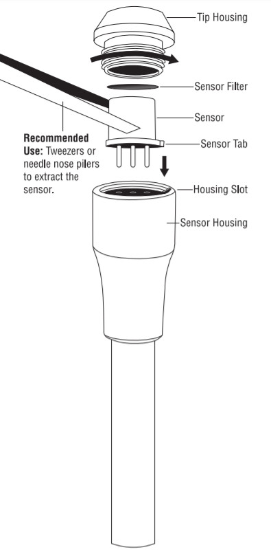
- Remove the sensor housing cap by turning it counterclockwise.
- With a pair of tweezers or a needle nose pair of pliers gently pull the sensor away from its socket.
- Inspect the inside of the sensor housing and verify that there is an O-ring over the socket and that no dirt or debris is present. If there is dirt or debris, gently pull the O-ring out, use a dry cotton swab to loosen the dirt, and blow with compressed air. Clean the O-ring and replace it.
![]() Do not cover the O-ring with Vaseline or any other lubricant.
Do not cover the O-ring with Vaseline or any other lubricant.
- Install the replacement sensor. Orient the tab on the edge of the sensor so it coincides with the groove on the side of the housing and gently pushes the sensor in.Do not use silicone-based hand cleaners or lotions prior to installing a new sensor as this will irreversibly affect its operation.
- Remove and discard the filter inside the sensor housing’s cap. Replace with a new filter disk, making sure no dirt, water, oil, or any other substance comes in contact with the filter. In the case of the J2791 sensor cap, it is recommended to first clean the sensor housing cap with alcohol or some other solvent that does not contain oil or silicone. Use a cotton swab to first loosen any debris from the cap’s opening. Finish by blowing with dry, oil-free, compressed air. Re-attach the cap to the sensor housing, screwing it finger tight. The water vapor filter cap should not be cleaned with solvents. Replace the paper filter only.
![]() Do not use acetone or silicone-based solvents, lotions, or un-cured adhesives while handling the sensor.
Do not use acetone or silicone-based solvents, lotions, or un-cured adhesives while handling the sensor.
Sensor Replacement Diagram
|
Replacement Parts |
|
| EMOS2 | Replacement EMOS sensor |
| LS2XVF | Water vapor filter |
WARRANTY
CPS®Products, Inc., guarantees that all products are free of manufacturing and material defects for two years. If the equipment should fail during the guarantee period it will be repaired or replaced (at our option) at no charge. This guarantee does not apply to equipment that has been altered, misused, or returned solely in need of field service maintenance. This repair policy does not include equipment that is determined to be beyond economical repair. All products being returned for warranty repair must be accompanied by an original bill of sale and customer contact information.
CPS Products, Inc.
CPS Products, Inc. U.S.A. (Headquarters)1010 East 31st Street, Hialeah, Florida 33013, USA Tel: 305-687-4121, 1-800-277-3808, Fax: 305-687-3743 E-mail: [email protected] Website: www.cpsproducts.comCPS CANADA LTD.6934 Kinsmen Court, Unit C, Niagara Falls, Ontario L2E 3S5 Tel: 905-358-3124, Fax: 905-358-7187, 1-866-629-3895, E-mail: [email protected]CPS PRODUCTS N.VKrijgsbaan 241, 2070 Zwijndrecht, Belgium Tel: (323) 281 30 40, Fax: (323) 281 65 83, E-mail: [email protected] Website: www.cpsproducts.beCPS AUSTRALIA PTY. LTD.109 Welland Avenue, Welland, South Australia 5007 Tel: +61 8 8340 7055, Fax: +61 8 8340 7033 E-mail: [email protected]CPS ASIA87 Bukit Timah Road, Unit B2, Singapore 229834 Tel: (65) 63375691, Fax: (65) 63375692 E-mail: [email protected]
![]()
References
[xyz-ips snippet=”download-snippet”]