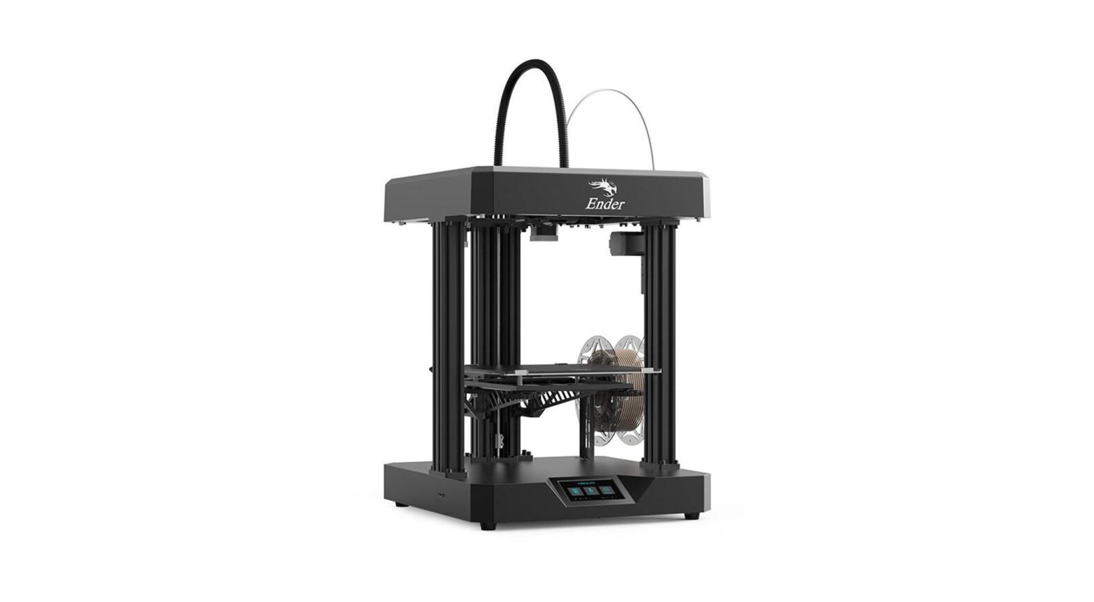
Ender-7 3D Printer
Create realityachieve dreamsEnder-7Ender-73D Printer User Manual3DV1.1
Dear Consumers,Thank you for choosing our products.For the best experience,please read the instructions before operating the printer. Our teams will always be ready to render you the best services. Please contact us via the phone number or e-mail address provided at the end when you encounter any problem with the printer. For a better experience in using our product, you can also learn how to use the printer in the following ways: View the accompanied instructions and videos in the storage card. Visit our official website www.creality.com to find relevant software/hardware information,contact details and operation and maintenance instructions.(www.cxsw3d.com)Firmware Upgrade Please login the official website https://www.creality.com/download, switch the language and select the relevant printer and model and download the required firmware, you can use it after the installation is finished.https://www.cxsw3d.com
NOTES1 Do not use the printer any way other than described herein in order to avoid personal injury or property damage. 2 Do not place the printer near any heat source or flammable or explosive objects. We suggest placing it in a well-ventilated, low-dust environment. 3 Do not expose the printer to violent vibration or any unstable environment, as this may cause poor print quality. 4 Before using experimental or exotic filaments, we suggest using standard filaments such as ABS or PLA to calibrate and test the machine. 5 Do not use any other power cable except the one supplied. Always use a grounded three-prong power outlet. 6 Do not touch the nozzle or printing surface during operation as they may be hot. Keep hands away from machine while in use to avoid burns or personal injury. 7 Do not wear gloves or loose clothing when operating the printer. Such cloths may become tangled in the printers moving parts leading to burns, possible bodily injury, or printer damage. 8 When cleaning debris from the printer hotend, always use the provided tools. Do not touch the nozzle directly when heated. This can cause personal injury. 9 Clean the printer frequently. Always turn the power off when cleaning, and wipe with a dry cloth to remove dust, adhered printing plastics or any other material off the frame,guide rails, or wheels. Use glass cleaner or isopropyl alcohol to clean the print surface. 10 Children under 10 years old should not use the printer without supervision. 11 This machine is equipped with a security protection mechanism. Do not manually move the nozzle or printing platform mechanism manually while bootingup, otherwise the device will automatically power off for safety. 12 Users should comply with the laws and regulations of the corresponding countries and regions where the equipment is located (used), abide by professional ethics, pay attention tosafety obligations, and strictly prohibit the use of our products or equipment for any illegal purposes. Creality will not be responsible for any violators’ legal liability under any circustance.1 ; 2 ; 3 ; 4 5 ; 6 7 8 9 10 10; 11 ; 12
ContentsIntroduction Parameters Parts List Assemble the 3D Printer 3D Use the 3D Printer 3D Start Printing Maintenance Equipment Maintenance Circuit Wiring Trouble-shooting
01-01 02-02 03-04 05-15 16-21 22-24 25-25 26-26 27-27 28-29
1. Introduction1 23 4 51 2 Upper Cover 3 4 5 6 701
6 789
10 11
8
9
10
11
12 Bellows 13
14 X
X
12 16
17
1813 19
14
20
1515 Storage card slot & Type-C interface &Type-C16 Teflon tube 17 Y Axis Limit Switch Y 18 19 Sliding rails 20 E Axis Motor E
2. Equipment Parameters
Model | Printing Size | Molding Tech | Nozzle Number | Slice Thickness | Nozzle Diameter |Precision | Filament | File Format | File Transfer | Slice Software | Rated Valtage| Rated Power | Bed Temp | Nozzle Temp | Resume Printing |Filament Detector | Language |Operating System | Printing Speed |
Basic ParametersEnder-7 250*250*300mm FDM 1 0.1mm-0.4mm Standard 0.4mm | 0.4mm ±0.1mm 1.75mm PLA STL/OBJ/AMF USB/Storage card | Creality Slicer/Cura/Repetier-Host/Simplify3D Input| :AC115/230V 50/60Hz Output|:DC 24V 350W 100 260 Yes | Yes | / English/ Español/ Deutsche/ Français/ P/ Português/ Italiano/ Türk Windows XP/7/8/10 MAC/Linux 250mm/s
02
3. Parts List
Z-axis Component Z
7 Top component03
8 Filament Holder
6 Z-axis Cover Z9 Z-axis profile Z
3. Parts List
10
11
×12
12
13
M4*10 Hexagon flat round
14
15 head screw x2
16
17
M4*10
18
19
20
21
22
18
M5*18
x 24
23 Cable connectors x 3
24 Serrated lock washers x 2
25 Power cord
Tips: the above accessories are for reference only, in kind prevail! 04
4. Install Profile51
5 Z-axis component Z
22
18
x 4
M5*18
24 Serrated lock washers x 105
4. Install Profile99 Z-axis profile Z
22
18
x 8
M5*18
06
5. Install the Printing Platform×8 1307
5. Install the Printing Platform×4 1308
6. Install Top Component
7 Top component
22
18
x 4
M5*18
24 Serrated lock washers x 1
09
6. Install Top Component
22
18
x 8
M5*18
10
7. Install Filament Holder8 Filament HolderM4*10 Hexagon flat round 15 head screw x2M4*1011
8. Install Z-axis Cover Z6 Z-axis Cover Z
Snap into place in the direction shown in the figure.
12
9. Cable Connection23 Cable connectors x 3 ×3
Securely insert the bellow into the mounting hole.Put the cable plug into the socket
Install the cable connectors13
9. Cable Connection
Connect the heated bed cable.
A
A B
Connect the Z-axis motor cable.
B
Z
Note: Align the male plug with the female plug and insert.14
10. Solution for V-wheel jamming of heated bed plate VGently dial the V-wheel manually to check whether it is idling. If idling happens, please use an open-ended wrench to adjust the off-center separation pillar according to the illustrated direction, so that the V wheel is not idling. VV Click back to the origin in the interface after power-on, and then go on moving the Z axis independently. Put your hand on the printing platform to observe whether the platform is stuck. If it is, please adjust the off-center separation pillar in the opposite direction according to the illustrated direction to make the V-wheel move smoothly. Z15
11. Bed Leveling
20 0
20 0
20 0
20 0
16
11. Bed Leveling
17
11. Bed Leveling18
12. Preheating
20 0
20 0
20 0
20 0
20 0
20 0
0 28 0 30
19
200
20 0
20 0
0 28 0 30
200
13. Load Filament14
14 20
13. Load Filament21
Method 1: Insert the new filament into filament runout detection module, the indicator light is on. Click the “Resume after filament runout” in the display, and set the nozzle temperature to 200. Take out the remaining filament in the filament runout detection module from the lower part of the extruder after the temperature rises. Push the extruding clamp until the filament is sent into the nozzle through the filament runout detection module. Method 2: Insert the new filament into filament runout detection module, the indicator light is on, then click the “Resume after filament runout” in the display. When it starts to print, hold the filament and allow it to go through the extruder. (The filament may not be properly fed into the Teflon tube due to bending or other reasons, resulting in failure of resumption).1 200 2
14. Start Printing252 252 302252 252 30222
14. Start Printing
This machine can print at a fast speed, but it is recommended to print at normal speed!Notes: the temperature of the nozzle is set according to the printing speed. Take PLA as an example: PLA
Cutting speedNozzle temperature
60mm/sAround 200 200
125mm/sAround 210 210
250mm/sAround 220 220
The printing temperature is different owing to the variety of PLA filaments. Please refer to the actual situation.
23
14. Start Printingstorage Warning: Please don’t insert or remove the storage card during printing.24
15.Maintenance- disassemble the upper cover —
First move the nozzle unit to where close to the origin .
Diagram 1: Remove the screws used for fixing of top cover, 1 Diagram 2: Press the position indicated by red arrow from the inside, 2open the buckles on both sides of the top cover and move them upward simultaneously disengage the buckles, and the top cover is removed.
Diagram 1: Move the nozzle unit to where close to the origin first before assembly.1 Diagram 2: Then align the positioning pins of the upper cover with the holes of the mounting plate. 2 Press the upper cover down again, and then lock the removed screws to the corresponding positions.
Diagram 1 125
Diagram2 2
Diagram 1 1
Diagram 2 2
16.Equipment MaintenanceMaintenance of sliding rails/ sliding blocks: Three sliding rails and sliding blocks in the X/Y line should be periodically maintained (generally per 3-6 months). When surfaces of sliding rails lack the lubricant or there is abnormal sound during the operation, it means that balls in sliding blocks lack the lubricant and lubricating grease or lubricating fluid should be applied on the sliding rails. / X/Y3-626
17. Circuit Wiring
Y signal cable interface Y X signal cable interface XFuse Normally open fan DC24V power input DC24V27
Heating tube
E E
Motor wire
Storage CardType-CControllable fan Display interface Auto leveling interface
18. Trouble-shootingPlay by menory storage cardmotorExtrusion gear loosemotor 28
18.29
Scan To Learn More
SHENZHEN CREALITY 3D TECHNOLOGY CO., LTD.Add:18F,JinXiuHongDu Building, Meilong Blvd., Longhua Dist., Shenzhen, China 518131 Official Website: www.creality.com Tel+86 755-8523 4565E-mail: info@creality.com cs@creality.com
 report this ad
18F www.cxsw3d.com 400 6133 882 0755-8523 4565
References
[xyz-ips snippet=”download-snippet”]