
CRESTRON RMC4 4-Series Control System
![]()
4-Series™ Control SystemThe Crestron® RMC4 provides a secure, high performance, cost-effective 4-Series™ control processor and interface for controlling and monitoring a single display device, a small AV system, lighting and shading, climate control, security, energy management, and many other specialized applications. A small form factor allows the RMC4 to be placed just about anywhere, with the option to attach it to a flat surface or DIN rail using the included mounting bracket.
In the Box
1 RMC4, 4-Series Control System
Additional Items
- 1 Bracket, Mounting, Integrated DIN Rail Clip (4519035)
- 2 Screw, 6-32 x 3/8 in., Phillips (2007225)
- 2 Connector, 3-Pin (2003575)
- 2 Connector, 4-Pin (2003576)
- 1 Connector, 5-Pin (2003577)
Mount the Control System
The RMC4 can be mounted onto a flat surface or a standard DIN rail using the included mounting bracket.
CAUTION: To prevent overheating, do not operate the RMC4 in an area that exceeds the environmental temperature range (32 to 104 °F or 0 to 40 °C) for this device.
Optional rack mount and pole mount kits (not included) are also available for use with the RMC4. For more information, refer to the RMK-IFE-1U Installation Guide (Doc. 7627) and the PLMK-IFE-101 Installation Guide (Doc. 7615).
Surface Mounting
- Detach the RMC4 from the mounting bracket by pulling the left and right flanges of the bracket outward to release the tabs that hold the RMC4 in place.
- Attach the mounting bracket to the surface by using four appropriate mounting screws (not included) through the four mounting holes on the bottom of the bracket.
- Align the slots on the bottom of the RMC4 with the tabs on the mounting bracket.
- Press the RMC4 into the bracket until it snaps into place.
- (Optional) Secure the RMC4 to the bracket using the two included 6-32 x 3/8 in. screws as shown in the following illustration.

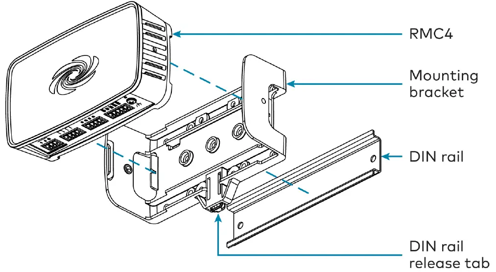
DIN Rail Mounting
- Detach the RMC4 from the mounting bracket by pulling the left and right flanges of the bracket outward to release the tabs that hold the RMC4 in place.
- Pull the DIN rail release tab downward using a flat-head screwdriver.
- Position the DIN rail mounting tabs (located on the rear of the bracket) over the top edge of the DIN rail.
- Push the DIN rail release tab upward to lock the mounting bracket onto the rail.
- Align the slots on the bottom of the RMC4 with the tabs on the mounting bracket.
- Press the RMC4 into the bracket until it snaps into place.
NOTE: Do not use the included screws to secure the bracket to the bottom of the RMC4 when mounting into a DIN rail, as it will then not be possible to remove the RMC4 from the DIN rail.
Connect the Control System
Make all device connections as shown in the following illustrations.
Front Panel Connections
Rear Panel Connections

Observe the following when connecting the RMC4:
- Power is provided to the RMC4 by a single Ethernet cable. A Crestron PoE (Power over Ethernet) power supply, such as the PWE-4803RU, or a PoE-capable network switch is recommended (both not included).
- Connect the chassis ground lug to a known earth ground circuit (for example, building steel) to ensure that the RMC4 is grounded properly.
- Apply power after all connections have been made.
COM 1 Connections
Port RS-232 RS-4221 RS-485G GND GND GND2
| TX | TX (from RMC4) | TX- (from RMC4) | TX-/RX- |
| RX | RX (to RMC4) | RX+ (from RMC4) | Not used |
| RTS | RTS (from RMC4) | TX+ (from RMC4) | TX+/RX+ |
| CTS | CTS (to RMC4) | RX- (to RMC4) | Not used |
- RS-422 transmit and receive are balanced signals that require two lines plus a ground in each direction. RXD+ and TXD+ should idle high (going low at start of data transmission). RXD- and TXD- should idle low (going high at start of data transmission). If necessary, RXD+/RXD- and TXD+/TXD- may be swapped to maintain correct signal levels.
- A ground terminal connection is recommended but not required.
Configure the Control System
The control system may be configured using the provided web configuration interface. The interface can be accessed using the control system IP address or the Crestron XiO Cloud® service.
Configuration via IP Address
To access the web configuration interface using the control system IP address:NOTE: The control system ships with DHCP enabled. A DHCP server is required to access the web configuration interface via the device IP address.
- Connect the control system to the network.
- Use the Device Discovery tool in Crestron Toolbox™ software to discover the control system and its IP address on the network.
- Enter the control system IP address into a web browser.
Configuration via Crestron XiO Cloud
The Crestron XiO Cloud service allows supported Crestron devices across an enterprise to be managed and configured from one central and secure location in the cloud. Supported devices are configured to connect to the service. Use of the service requires a registered Crestron XiO Cloud account.NOTE: The device may be disconnected from the service by navigating to the Cloud Services tab in Crestron Toolbox software (Functions > Device Info > Cloud Services). For details, refer to the Crestron Toolbox help file.
To access the web configuration interface using the Crestron XiO Cloud service:
- Connect the control system to the network.
- Record the MAC address and serial number that are labeled on the top of the control system. The MAC address and serial number are required to add the device to the service.
- Do either of the following
- For existing accounts, access the Crestron XiO Cloud service at https://portal.crestron.io.
- For new accounts, register for a Crestron XiO Cloud account at www.crestron.com/xio-cloud-registration.
- Claim the device to the service as described in the Crestron XiO Cloud User Guide (Doc. 8214).
- Select the device from the cloud interface to view its settings.
Create an Admin AccountThe first time the web configuration interface is accessed, a dialog box is displayed asking the user to create an admin account. A similar message is displayed when connecting to the device in Crestron Toolbox software ifan admin account has not already been created.To create an admin account:
- Enter a username and password for the admin account in the appropriate text fields.CAUTION: Do not lose the username and password for the admin account, as the device must be reset to factory settings to regain access.
- Click OK. A dialog box is displayed stating that enabling authentication will restart the web session.
- Click Yes to confirm and restart. The username and password created in step 1 must be entered to regain access to the web configuration interface.NOTE: The username and password must also be entered when connecting to Crestron Toolbox or XPanel.
Set the Time ZoneThe time zone must be set on the control system to ensure that the correct time settings are pushed to controlled devices.To set the time zone:
- Access the web configuration interface using either the device IP address or the Crestron XiO Cloud service.
- Navigate to Settings > System Setup.
- Select the time zone where the control system is used from the Time Zone drop-down menu.
- Click Save Changes on the top right of the screen.
Pair with Apple HomeKitThe control system can be paired with Apple® HomeKit® technology to enable communication between the control system and Apple HomeKit devices and accessories.For pairing instructions and to locate the unique QR code required for pairing, refer to the RMC4 Product Information document (Doc. 8541) that shipped with the RMC4.
Visit the Product Pagewww.crestron.com/model/6510418
Additional Information
Original InstructionsThe U.S. English version of this document is the original instructions.All other languages are a translation of the original instructions.
Crestron product development software is licensed to Crestron dealers and Crestron Service Providers (CSPs) under a limited nonexclusive, nontransferable Software Development Tools License Agreement. Crestron product operating system software is licensed to Crestron dealers, CSPs, and end-users under a separate End-User License Agreement. Both of these Agreements can be found on the Crestron website at www.crestron.com/legal/software_license_agreement.
The product warranty can be found at www.crestron.com/warranty.
The specific patents that cover Crestron products are listed at www.crestron.com/legal/patents
Certain Crestron products contain open source software. For specific information, visit www.crestron.com/opensource
Crestron, the Crestron logo, 4-Series, Cresnet, Crestron Toolbox, and XiO Cloud are either trademarks or registered trademarks of Crestron Electronics, Inc. in the United States and/or other countries. Apple and HomeKit are either trademarks or registered trademarks of Apple, Inc. in the United States and/or other countries. Other trademarks, registered trademarks, and trade names may be used in this document to refer to either the entities claiming the marks and names or their products. Crestron disclaims any proprietary interest in the marks and names of others. Crestron is not responsible for errors in typography or photography.©2020 Crestron Electronics, Inc.Doc. 8513A06/26/20
report this ad![]()
[xyz-ips snippet=”download-snippet”]