USB-EXT-2-LOCAL/USB-EXT-2-REMOTEUSB over Category Cable ExtendersQuick Start
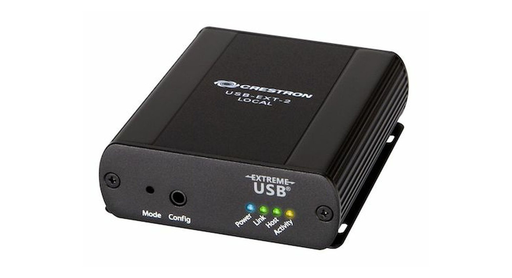
The Crestron® USB over Category Cable Extenders (USB-EXT-2-LOCAL and USB-EXT-2-REMOTE) delivers reliable, high-speed USB signal extension for USB 1.1 and 2.0 devices in a conference room, classroom, auditorium, command center, medical facility, public space, or residence. Without requiring any special configuration or drivers, the USB extenders enable wire runs up to 330 ft (100 m) over a single CAT5e (or better) unshielded twisted-pair (UTP) cable. The USB extenders support most USB device types and are plug-and-play compatible with computers running Windows®, macOS®, and Linux® operating systems.The USB-EXT-2-LOCAL and USB-EXT-2-REMOTE are functionally similar. For simplicity within this guide, the term “USB extender” is used except where noted. The USB extenders are also compatible with the USB over Category Cable Extender Wall Plates (USB-EXT-2-LOCAL-1G and USB-EXT-2-REMOTE-1G).
In the Box
1 USB-EXT-2-LOCAL or USB-EXT-2-REMOTEAdditional Items1 Kit, Mounting Hardware
USB-EXT-2-REMOTE Only1 Adapter, Power, 24 VDC, 1 A, 100-240 VAC1 Power Cable, 6 ft (1.83 m)
USB-EXT-2-LOCAL Only1 Cable, USB 2.0 A-B, 6 ft (1.83 m)
Quick Start
 Install the USB ExtenderTo complete the USB extender installation, follow the sections below to connect the USB-EXT-2-LOCAL to the USB-EXT-2-REMOTE, mount the USB extenders, connect the USB devices to the extenders, and verify the installation.Connect the USB ExtendersConnect the USB-EXT-2-LOCAL extender to the USB-EXT-2-REMOTE extender.
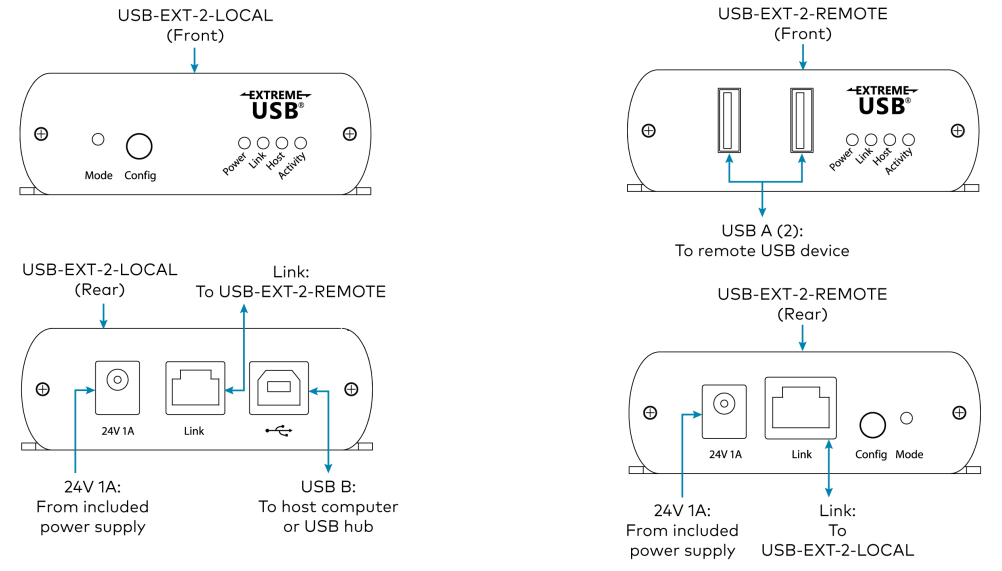
- Connect one RJ45 connector end of the CAT5e (or better) cable to the Link port on the USB-EXT-2-LOCAL, and then connect the other RJ45 connector end to the Link port on the USB-EXT-2-REMOTE. The maximum cable distance is 330 ft (100 m).CAUTION: The USB-EXT-2-LOCAL and USB-EXT-2-REMOTE are intended for use as point-to-point USB extenders and must not be connected to an Ethernet LAN or any other network device via the Link Port.NOTES:• To comply with the European Directive (CE), Crestron recommends using high-quality, solid core CAT5e (or better) shielded twisted pair (STP) cable.• The CAT5e (or better) cable must have a straight-through conductor configuration with no crossovers and must be terminated with 8-conductor RJ45 connectors at both ends.• If using preinstalled in-wall CAT wiring, connect one RJ45 connector end of a CAT5e (or better) patch cable to the Link port of the local extender and connect the other RJ45 connector end to the CAT wall outlet near the host computer. Then, connect one RJ45 connector end of a CAT5e (or better) patch cable to the Link port of the remote extender, and connect the other RJ45 connector end to the CAT wall outlet near the USB device(s). Ensure that the two patch cables and the in-wall cabling do not exceed 330 ft (100 m) in total.
- Using a USB 2.0 A to B cable (not included), connect the USB B end into the USB-EXT-2-LOCAL host port ( ), and then connect the USB A end of the cable into a USB Type-A port on the host device (USB 1.1 or 2.0 compatible).NOTE: The Config jack on the USB extender is reserved for factory use only.
- Connect the included power adapter to either the USB-EXT-2-LOCAL or the USB-EXT-2-REMOTE, and then plug the other end of the power adapter into an AC power source.NOTE: The power adapter must be connected to either the USB-EXT-2-LOCAL or USB-EXT-2-REMOTE, not both. Power is passed to the second device via the Link connection.
 Mount the USB ExtenderAfter determining the location of the local host computer and the remote USB device(s), decide the mounting method for the USB extender. The USB extender may be placed on a flat surface or mounted to a flatsurface or rack rail.Place onto a Flat SurfacePlace the USB-EXT-2-LOCAL on a secure, level surface near the host computer, and place the USB-EXT-2-REMOTE on a secure, level surface near the USB device(s). The rubber feet on the bottom of each extender help to prevent the extenders from shifting.Mount the USB Extender Using Mounting BracketsAttach the two supplied brackets to the rear of the USB extender using the four supplied Phillips head screws (two screws for each bracket).
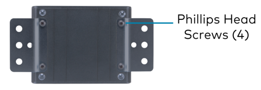
Using the two supplied brackets, mount the USB extender onto any of the following:
- Flat surface, such as a table or wall
- Rack rail
Mount onto a Flat SurfaceWith the two brackets attached to the USB extender, attach the brackets to a flat surface using the outer middle surface mount hole of eachbracket and the appropriate mounting screws (not supplied).
 Mount onto a Rack RailWith the two brackets attached to the USB extender, attach either the left or right bracket to the rack rail using the top and bottom rack mount holes and the appropriate mounting screws (not supplied).

Connect the USB Devices
- Install any software on the host computer that is required to operate the USB device(s). Refer to the USB device documentation forinstallation instructions.
- Using USB 2.0 cables (not supplied), connect the USB devices (USB 1.1 or 2.0 compatible) to the USB-EXT-2-REMOTE. Up to two USB devices may be connected.
- Confirm that each USB device is properly installed on the host computer and that it is detected by the operating system.NOTE: The USB extender is engineered to deliver maximum compatibility with the widest possible range of devices. Crestron doesnot guarantee that all USB devices or hosts are compatible with the USB extender.
Check the InstallationCheck that the Activity, Host, Link, and Power LEDs light on both the USB-EXT-2-LOCAL and the USB-EXT-2-REMOTE. If the Host or Link LEDs do not light, then the cabling between the USB extenders may be installed incorrectly or may be defective.The following table describes the behavior of the LEDs on the front panel of the USB extender.
| LED | Color | Description |
| Activity | Flashing amber | Data transmission is occurring between the USB-EXT-2-LOCAL and the USB-EXT-2-REMOTE. |
| Host | Solid green | The host device is recognizing the USB extender. |
| Link | Solid green | A valid link is established between the USB extender. |
| Fast-flashing green | The USB extender is in Pairing mode. | |
| Slow-flashing green | The USB extender is attempting to establish a link. | |
| Power | Blue | The USB extender is receiving power. |
Additionally, check to see whether USB extender system has been installed correctly on the host computer. Refer to the below instructions.For Windows Software:
- Open Device Manager.
- Expand the Universal Serial Bus controllers node.
- Check to see if the extender system appears on the list of controllers.If the extender system has been properly installed, it appears on the list as a “Generic USB Hub.”
For macOS Software:
- Open System Profiler.
- In the left column under Hardware, select USB.
- Check to see if the extender system appears in the USB Device Tree at the top right of the System Profiler window. If the extender system has been properly installed, it is listed as a “Hub” under the USB HighSpeed Bus/USB Bus node.If the USB extender system does not detect correctly or fails to detect, refer to “Troubleshoot the USB Extender.”
 Troubleshoot the USB Extender
 Troubleshoot the USB Extender
The following table provides corrective actions for possible trouble situations. If further assistance is required, please contact a Crestron Customer service representative.
| Symptom | Issue | Action |
| The USB device is attached to the USB-EXT-2-REMOTE, butthe device does not function. | The USB device requires drivers that are not installed on the host computer. | Install the required USB device driver on the host computer operating system prior to attaching the USB device to the USB-EXT-2-LOCAL. Refer to theUSB device documentation for more information. |
| The USB device does not support USB hubs. | Check that the device displays in the Device Manager tool (Windows) or the System Profiler tool (macOS). | |
| The USB device has malfunctioned. | Refer to the USB device documentation for more information. | |
| An overcurrent condition has occurred because the USB device drew more power than can be supplied per the USB specification (1 A). | Cycle the power of the USB-EXT-2-REMOTE by unplugging the power adapter from the USB-EXT-2-REMOTE. Wait approximately 30 seconds, andthen plug the power adapter back into the remote extender.If the overcurrent condition continues to occur, the USB device may use more power than can be supplied per the USB specification, or the USB device may be damaged.Refer to the USB device documentation for powering the USB device with the required power adapter. | |
| The Link LEDs on theUSB-EXT-2-LOCAL and the USB-EXT-2-REMOTE do notlight. | The USB-EXT-2-LOCAL or the USB-EXT-2-REMOTE is not receiving power. | Ensure that the host computer is powered on and is properly connected to the USB-EXT-2-LOCAL.Ensure that the power adapter is properly connected to either the USB-EXT-2-LOCAL or the USB-EXT-2-REMOTE. |
| The CAT cable connecting the USB-EXT-2-LOCAL and the USB-EXT-2-REMOTE is malfunctioning. | Ensure that a CAT5e (or better) cable is properly installed.Replace the cable if necessary. | |
| The USB-EXT-2-LOCAL or the USB-EXT-2-REMOTE is malfunctioning. | Ensure that the power adapter is connected to a live source of electrical power. |
 Visit the Product PageScan the QR code to visit the product page.
USB-EXT-2-LOCAL

https://www.crestron.com/model/6511093
USB-EXT-2-REMOTE

https://www.crestron.com/model/6511094
Additional Information
Original InstructionsThe U.S. English version of this document is the original instructions.All other languages are a translation of the original instructions.Crestron product development software is licensed to Crestron dealers and Crestron Service Providers (CSPs) under a limited nonexclusive, nontransferable Software Development Tools License Agreement. Crestron product operating system software is licensed to Crestron dealers, CSPs, and end-users under a separate End-User License Agreement. Both of these Agreements can be found on the Crestron website at www.crestron.com/legal/software_license_agreement.The product warranty can be found at www.crestron.com/warranty.The specific patents that cover Crestron products are listed at www.crestron.com/legal/patents.Certain Crestron products contain open-source software. For specific information, visit www.crestron.com/opensource.Crestron and the Crestron logo are either trademarks or registered trademarks of Crestron Electronics, Inc. in the United States and/or other countries. macOS is either a trademark or registered trademark of Apple, Inc. in the United States and/or other countries. Extreme USB is either a trademark or registered trademark of Icron Technologies Corporation in the United States and/or other countries. Linux is either a trademark or a registered trademark of Linus Torvalds in the United States and/or other countries. Windows is either a trademark or registered trademark of Microsoft Corporation in the United States and/or other countries. Other trademarks, registered trademarks, and trade names may be used in this document to refer to either the entities claiming the marks and names or their products. Crestron disclaims any proprietary interest in the marks and names of others. Crestron is not responsible for errors in typography or photography.©2020 Crestron Electronics, Inc.Doc ID 8565A205483002/14/20
[xyz-ips snippet=”download-snippet”]