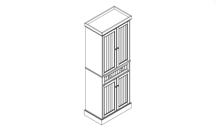

Pantry CF3114

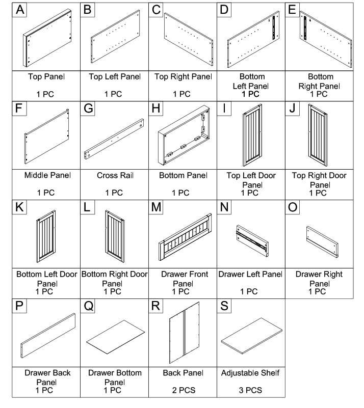
PART LIST
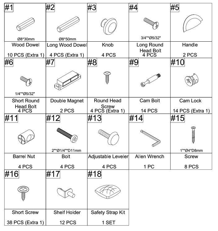
HARDWARE LIST
ADDITIONAL TOOLS (Not Provided)Note: It is not recommended to use power tools during assembly.
 Note: Wood dowels are intended for alignment. Additional clearance between wood dowel and pre-drilled hole is intentional for ease of assembly.
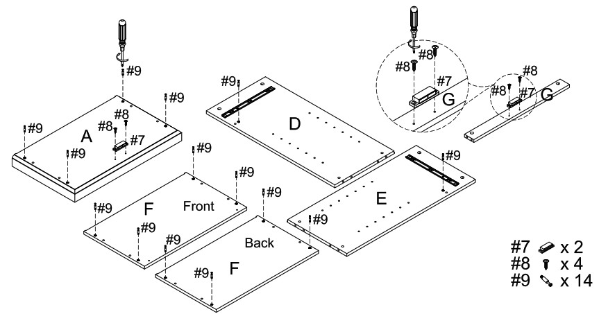
Step 1. Attach double magnets (part #7) to top panel (part A) and cross rail (part G) using round head screws (part #8) and phillips head screwdriver. Attach cam bolts (part #9) to top panel (part A), bottom panels (parts D & E) and middle panel (part F) using phillips head screwdriver.
NOTE: Do not overtighten cam bolts. Stop tightening once threads on cam bolt are no longer visible.
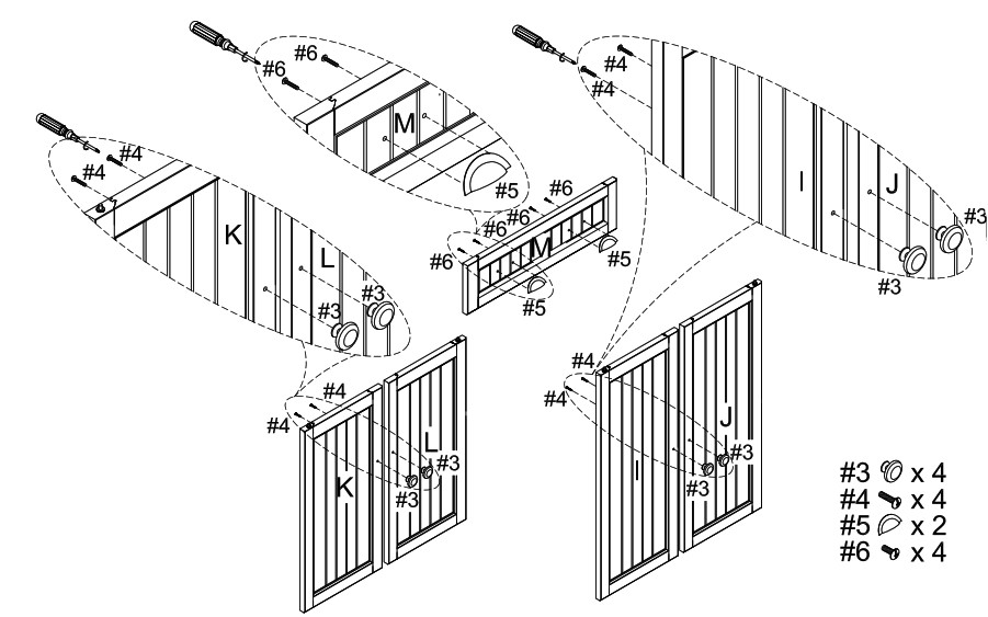
Step 2. Attach handles (part #5) to drawer front panel (part M) using short round head bolts (part #6) and phillips head screwdriver. Attach knobs (part #3) to door panels (parts I, J, K & L) using long round head bolts (part #4) and phillips head screwdriver. 41kt.
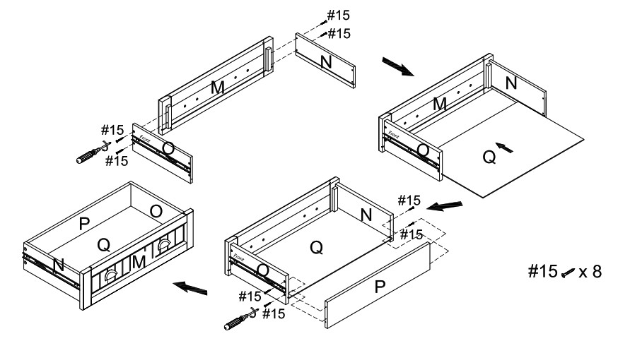
Step 3. Attach drawer panels (parts N & 0) to drawer front panel (part M) using screws (part #15) and phillips head screwdriver. Slide drawer bottom panel (part C1) into grooves of assembled unit (parts M, N & 0). Attach drawer back panel (part P) to assembled unit (parts N, 0 & Q) using screws (part #15) and phillips head screwdriver.
 Step 4. Attach top left panel (part B) and top right panel (part C) to top panel (part A) using wood dowels (part #1) and cam locks (part #10).
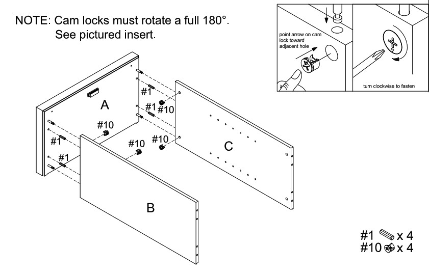
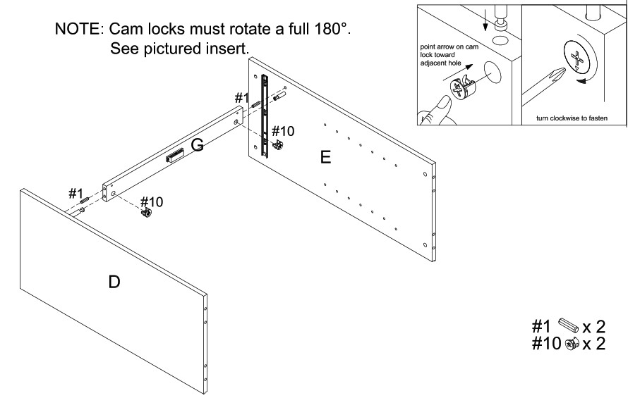
Step 5. Attach middle panel (part F) to top left panel (part B) and top right panel (part C) using long wood dowels (part #2) and cam locks (part #10).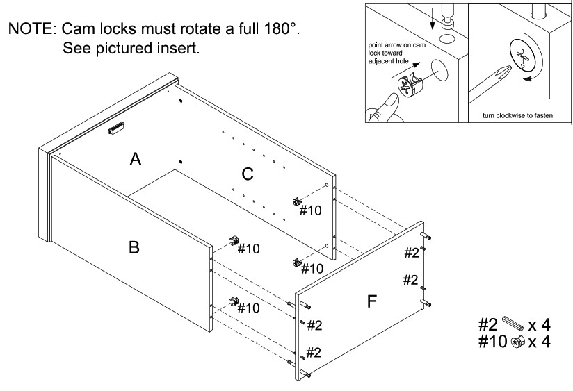 Step 6. Attach cross rail (part G) to bottom left panel (part D) and bottom right panel (part E) using wood dowels (part #1) and cam locks (part #10).
Step 7. Attach assembled unit (parts D& E) to middle panel (part F) using cam locks (part #10)
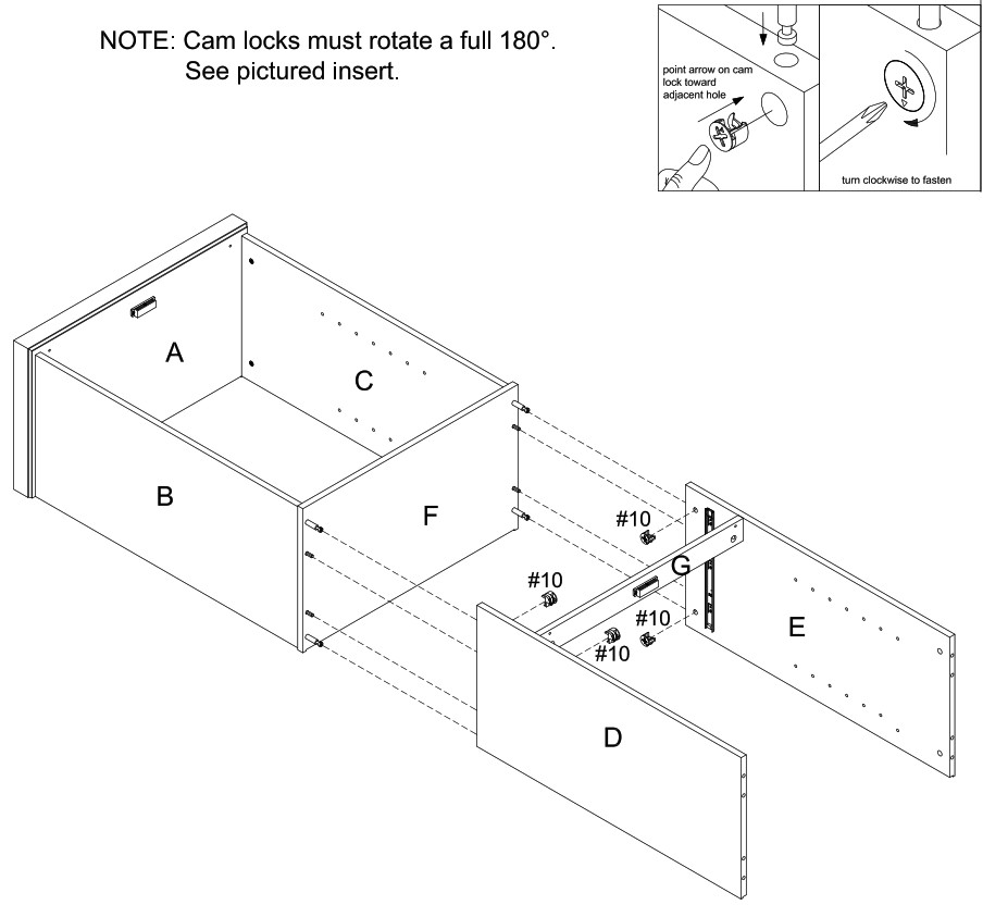
#10 x 4
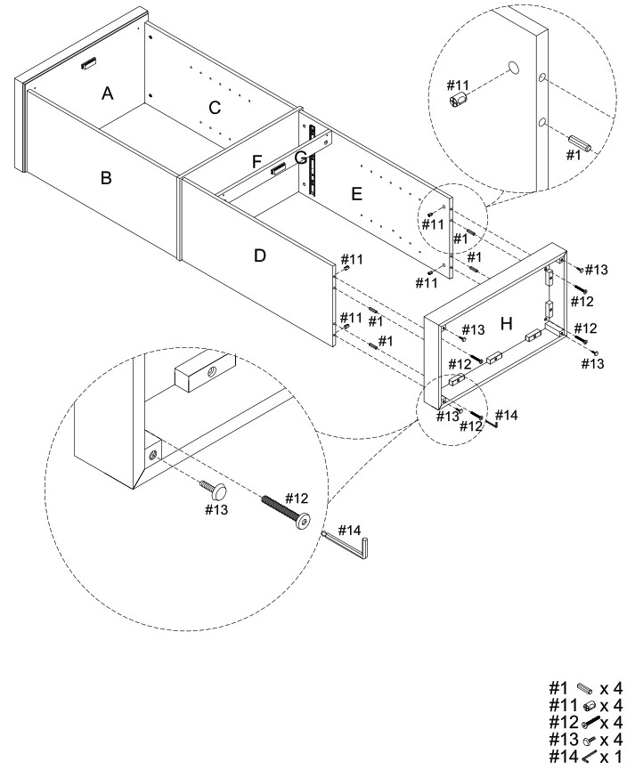
Step 8. Attach bottom panel (part H) to assembled unit (parts D & E) using wood dowels (part #11), bolts (part #12) and Allen wrench (part #14). Attach adjustable levelers (part #13) to bottom panel (part H).
Step 9. Carefully turn unit upright. Attach back panels (part R) to assembled unit (parts A, B, C, D, E, F & H) using short screws (part #16) and phillips head screwdriver.

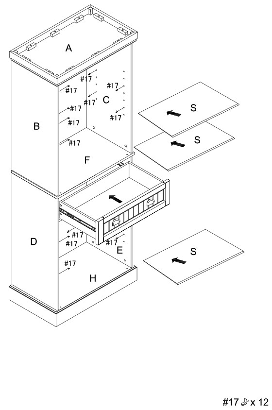
Step 10. Place shelf holders (part #17) into desired position and then slide adjustable shelves (part S) into place. Slide assembled drawer into place.
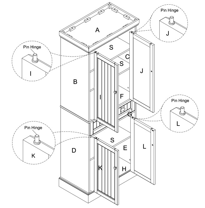
Step 11. Attach door panels (parts I, J, K & L) by placing bottom pin hinge (pre-installed in door) in the pre-drilled hole of middle panel (part F) and bottom panel (part H). Then depress the top spring-loaded pin hinge so it can be placed in the pre-drilled hole of top panel (part A) and cross rail (part G).
NOTE: Be sure top and bottom pin hinges are fully extended to secure doors in place.NOTE: It is important to adjust levelers once fully assembled and upright. Extend adjustable leveler until it’s firmly in contact with the floor. If relocating, adjust leveler as needed until it’s firmly in contact with the floor in new location.
Important: Safety strap kit (part #18) must be installed to prevent tipping, damage, and/or injury.
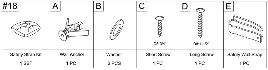
SAFETY WALL STRAP INSTALLATION
Note: It is highly recommended to install this safety strap kit to prevent tipping, damage, and/or injury.
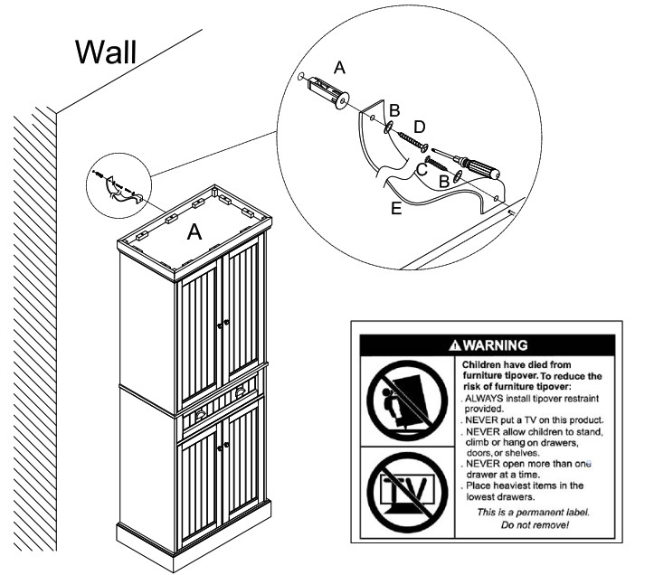
- Insert short screw (C) through washer (B) and safety wall strap (E) and attach to top panel (part A) using phillips head screwdriver.
- Drill a 11/32″ hole where you want to secure the unit. The drilled hole will be at the same height as the hole in top panel (part A) where the safety wall strap (E) is attached. Tap wall anchor (A) into the hole.
- Insert long screw (D) through washer (B) and safety wall strap (E) into wall anchor (A) using phillips head screwdriver.
Note: This item is not intended for clothing storage use.
[xyz-ips snippet=”download-snippet”]