
CyberPower® CP850PFCLCD/CP1000PFCLCD User’s Manual
K01-0000160-04
PRODUCT REGISTRATION
Thank you for purchasing a CyberPower product. Please take a few minutes to register your product at www.cyberpower.com/registration. Registration certifies your product’s warranty, confirms your ownership in the event of a product loss or theft and entitles you to free technical support. Register your product now to receive the benefits of CyberPower ownership.
IMPORTANT SAFETY WARNINGS
(SAVE THESE INSTRUCTIONS)
This Manual Contains Important Instructions that should be followed during Installation and Maintenance of the UPS and batteries.
CAUTION! To prevent the risk of fire or electric shock, install in a temperature and humidity controlled indoor area free of conductive contaminants. (Please see specifications for acceptable temperature and humidity range).
CAUTION! To reduce the risk of electric shock, do not remove the cover except to service the battery. Turn off and unplug the unit before servicing the batteries. There are no user serviceable parts inside except for the battery.
CAUTION! Hazardous live parts inside can be energized by the battery even when the AC input power is disconnected.
CAUTION! The UPS must be connected to an AC power outlet with fuse or circuit breaker protection. Do not plug into an outlet that is not grounded. If you need to de-energize this equipment, turn off and unplug the unit.
CAUTION! To avoid electric shock, turn off the unit and unplug it from the AC power source before servicing the battery or installing a computer component.
CAUTION! Not for use in a computer room as defined in the Standard for the Protection of Electronic Computer/Data Processing Equipment, ANSI/NFPA 75.
CAUTION! To reduce the risk of fire, connect only to a circuit provided with 20 amperes maximum branch circuit over current protection in accordance with the National Electric Code, ANSI/NFPA 70.
DO NOT USE FOR MEDICAL OR LIFE SUPPORT EQUIPMENT! CyberPower Systems does not sell products for life support or medical applications. DO NOT use in any circumstance that would affect the operation and safety of life support equipment, medical applications, or patient care.
DO NOT USE WITH OR NEAR AQUARIUMS! To reduce the risk of fire or electric shock, do not use with or near an aquarium. Condensation from the aquarium can cause the unit to short out.
DO NOT USE THE UPS ON ANY TRANSPORTATION! To reduce the risk of fire or electric shock, do not use the unit on any transportation such as airplanes or ships. The effect of shock or vibration caused during transit and the damp environment can cause the unit to short out.
INSTALLING YOUR UPS SYSTEM
INTRODUCTION
Thank you for selecting a CyberPower Systems UPS product. This UPS is designed to provide unsurpassed power protection, operation and performance during the lifetime of the product.
UNPACKING
Inspect the UPS upon receipt. The box should contain the following:
(a) UPS unit (b) User’s manual (c) Coaxial cable(d) USB A+B type cable (e) Function Setup Guide
*PowerPanel® Personal Edition software is available on our website. Please visit www.cyberpower.com and go to the Software Section for free download.
SUPPORTS Active PFC POWER SUPPLIES
This CyberPower UPS system supports High Efficiency power supplies with Active Power Factor Correction (Active PFC). Active PFC is used to improve the efficiency of power delivery. The current US Energy Star® Program Requirements for Computers (version 5.0) mandates Active PFC for all power supplies over 100 watts. Additionally, programs such as 80 Plus® are often used to identify high efficiency power supplies with Active PFC.
OVERVIEW
The CP850PFCLCD/CP1000PFCLCD provides complete power protection from utility power that is not always consistent. The CP850PFCLCD/CP1000PFCLCD features 1030 Joules of surge protection. Both units provide long lasting battery backup during power outages with maintenance free batteries. The CP850PFCLCD/CP1000PFCLCD ensures consistent power to your computer system and includes software that will automatically save your open files and shutdown your computer system during a utility power loss.
AUTOMATIC VOLTAGE REGULATOR
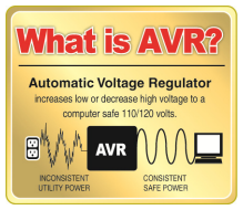 The CP850PFCLCD/CP1000PFCLCD stabilizes inconsistent utility power voltage to nominal levels that are safe for equipment. Inconsistent incoming utility power may be damaging to important data files and hardware, but with Automatic Voltage Regulation (AVR), damaging voltage levels are corrected to safe levels. AVR automatically increases low utility power and decreases high utility power to a consistent and safe 110/120 volts. If incoming utility voltage drops below 90 volts, or exceeds 140 volts the units automatically switch to battery back-up power.
HOW TO DETERMINE THE POWER REQUIREMENTS OF YOUR EQUIPMENT
- Ensure that the equipment plugged into the outlet does not exceed the UPS unit’s rated capacity (850VA/510W for CP850PFCLCD, 1000VA/600W for CP1000PFCLCD). If the rated capacities of the unit are exceeded, an overload condition may occur and cause the UPS unit to shut down or the circuit breaker to trip.
- There are many factors that can affect the amount of power that your computer system will require. It is suggested that the load placed on the battery outlets not exceed 80% of the unit’s capacity.
HARDWARE INSTALLATION GUIDE
- Your new UPS may be used immediately upon receipt. However, after receiving a new UPS, to ensure the battery’s maximum charge capacity, it is recommended that you charge the battery for at least 8 hours. Your UPS is equipped with an auto-charge feature. When the UPS is plugged into an AC outlet, the battery will automatically charge whether the UPS is turned on or off.

- Note: This UPS is designed with a safety feature to keep the system from being turned on during shipment. The first time you turn the UPS on, you will need to have it connected to AC power or it will not power up.
- With the UPS unit turned off and unplugged, connect your computer, monitor, and any other peripherals requiring battery backup into the battery power supplied outlets. DO NOT plug a laser printer, paper shredder, copier, space heater, vacuum, sump pump or other large electrical devices into the “Battery and Surge Protected Outlets”. The power demands of these devices may overload and damage the unit.
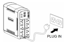
- Plug the UPS into a 2 pole, 3 wire grounded receptacle (wall outlet). Make sure the wall branch outlet is protected by a fuse or circuit breaker and does not service equipment with large electrical demands (e.g. air conditioner, copier, etc…). The warranty prohibits the use of extension cords, outlet strips, and surge strips.
- Press the power switch to turn the unit on. The Power On indicator light will illuminate and the unit will “beep”. If an overload is detected, an audible alarm will sound and the unit will emit one long beep. To correct this, turn the UPS off and unplug at least one piece of equipment from the battery power supplied outlets. Make sure the circuit breaker is depressed and then turn the UPS on.
- To maintain optimal battery charge, leave the UPS plugged into an AC outlet at all times.
- To store the UPS for an extended period, cover it and store with the battery fully charged. While in storage, recharge the battery every three months to ensure battery life.
- Insure the wall outlet and UPS are located near the equipment being attached for proper accessibility.
BASIC OPERATION
DESCRIPTION
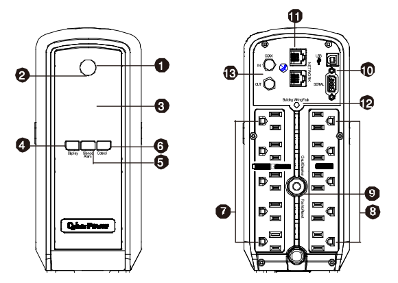
- Power SwitchUsed as the master on/off switch for equipment connected to the battery power supplied outlets.
- Power On IndicatorThis LED is illuminated when the utility power is normal and the UPS outlets are providing power, free of surges and spikes.
- LCD module displayHigh resolution and intelligent LCD display shows all the UPS information using icons and messages. For more information please review the “Definitions for Illuminated LCD Indicators” section below.
- Display switchThe switch can be used to select the LCD display contents including Input Voltage, Output Voltage, and Estimated Run Time. The toggle frequency is set to one time per 0.5 second. Press the switch to roll down the function menu. Pressing the switch for 2 seconds will turn the LCD display on or off while in AC/Utility power mode.
- Silence Alarm switchThe toggle frequency is set to one time per 0.5 second. Press the switch to roll up the function menu. Holding the switch for more than 2 seconds while running on battery will silence the buzzer.
- Control switchPress the Control switch for 3 seconds in AC/Utility Power Mode to perform a Self Test of the battery.
- Battery and Surge Protected OutletsThe unit has five battery powered/surge suppression outlets for connected equipment to ensure temporary uninterrupted operation of your equipment during a power failure. (DO NOT plug a laser printer, paper shredder, copier, space heater, vacuum, sump pump or other large electrical devices into the “Battery and Surge Protected Outlets”. The power demands of these devices may overload and damage the unit.)
- Full-Time Surge Protection OutletsThe unit has five surge suppression outlets.
- Circuit BreakerLocated on the back of the UPS, the circuit breaker serves to provide overload and fault protection.
- Serial/USB Ports to PCThe USB port allows connection and communication between the USB port on the computer and the UPS unit.
- Communication Protection PortsCommunication protection ports, bi-directional, will protect a 10/100/1000Ethernet connection(RJ45).
- Wiring Fault Indicator (red)This LED indicator will illuminate to warn the user that a wiring problem exists, such as bad ground, missing ground or reversed wiring. If this is illuminated, disconnect all electrical equipment from the outlet and have an electrician verify the outlet is properly wired. The unit will not provide surge protection without being plugged into a grounded and properly wired wall outlet.
- Coax/Cable/DSS Surge ProtectionThe Coax/Cable/DSS protection ports will protect any cable modem, CATV converter, or DSS receiver.
REPLACING THE BATTERY
Replacement of batteries located in an OPERATOR ACCESS AREA.
- When replacing batteries, replace with the same number of the following battery: CyberPower / RB1280A for the CP850PFCLCD; CyberPower / RB1290 for the CP1000PFCLCD.
- CAUTION! Risk of Energy Hazard, 12 V, maximum 9 Ampere-hour battery. Before replacing batteries, remove conductive jewelry such as chains, wrist watches, and rings. High energy conducted through these materials could cause severe burns.
- CAUTION! Do not dispose of batteries in a fire. The batteries may explode.
- CAUTION! Do not open or mutilate batteries. Released material is harmful to the skin and eyes. It may be toxic.
- CAUTION: A battery can present a risk of electrical shock and high short circuit current. The following precautions should be observed when working on batteries:
- Remove watches rings, or other metal objects.
- Use tools with insulated handles.
CAUTION – RISK OF EXPLOSION IF BATTERY IS REPLACED BY AN INCORRECT TYPE. DISPOSE OF USED BATTERIES ACCORDING TO LOCAL REGULATIONS.
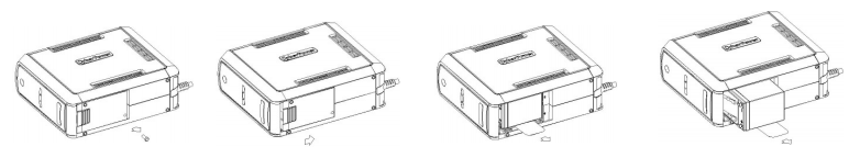
BATTERY REPLACEMENT PROCEDURE:
- Turn off and unplug all connected equipment.
- Turn the UPS off and unplug it from the AC power source.
- Turn the UPS on its side.
- Remove the retaining screw located on the bottom of the UPS.
- Slide the battery compartment cover completely off of the unit.
- Remove the batteries from the compartment.
- Disconnect the battery wires from the batteries.
- Install the replacement batteries by connecting the red wire (+) and black wire (-) to the same color connectors from the battery pack.
- Put the batteries back into the compartment.
- Slide back the battery compartment cover and tighten the retaining screw.
- Recharge the UPS for 8-16 hours to fully charge the battery.
REMINDER: Batteries are considered HAZARDOUS WASTE and must be disposed of properly. Most retailers that sell lead-acid batteries collect used batteries for recycling, as required by local regulations.
DEFINITIONS FOR ILLUMINATED LCD INDICATORS
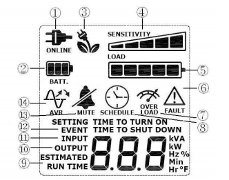
- ONLINE: The UPS is supplying utility power to connected equipment.
- BATTERY: During a severe brownout or blackout, this icon appears and an alarm sounds (two short beeps followed by a pause) to indicate the UPS is operating from its internal batteries. During a prolonged brownout or blackout, the alarm will beep rapidly every 1/2 second (and the BATT.CAPACITY meter shows one 20% capacity segment shaded. The capacity depends on how much load added and the runtime left.) to indicate the UPS’s batteries are nearly out of power. You should save files and turn off your equipment immediately or allow the software to shut the system down.
- Energy-Saving: The UPS in energy-saving bypass mode. See “CyberPower GreenPower UPSTM Technology” section for more information.
- LOAD capacity / Sensitivity setup: This meter displays the approximate output load level (in 20% increments) of the UPS battery outlets. It can also be sensitivity setup meter if you are in programming mode. It is to control the sensitivity of the UPS to switch to Battery Mode by selecting UPS shutdown voltage range. When the sensitivity is increased, the UPS will switch to Battery Mode with less input power variation.
- BATTERY capacity: This meter displays the approximate charge level (in 20% increments) of the UPS’s internal battery. During a blackout or severe brownout, the UPS switches to battery power, the BATTERY icon appears, and the charge level decreases.
- FAULT: This icon appears if there is a problem with the UPS. Press the POWER button to turn off the UPS.F01: Battery Mode or AC/Utility Power Mode Overload fault (Turn on the UPS again.)F02: Battery Output Short fault (Turn on the UPS again.)F03: Charger Fault (Contact CyberPower Systems for support.)F04: Internal Fault (Contact CyberPower Systems for support.)
- OVER LOAD: This icon appears and an alarm sounds to indicate the battery-supplied outlets are overloaded. To clear the overload, unplug some of your equipment from the battery-supplied outlets until the icon turns off and the alarm stops.
- SCHEDULE: Users can setup the schedule to turn on and shut down the computer and UPS through PowerPanel® Personal Edition software. The LCD display will show how much time is left before the UPS will turn back on or shut down.
- ESTIMATED RUNTIME: This displays the run time estimate of the UPS with current battery capacity and load.
- OUTPUT meter: This meter measure, in real time, the AC voltage that the UPS system is providing to the computer, such as normal AC line mode, AVR mode, and battery backup mode. (Note: The OUTPUT meter shows the status of the battery backup outlets in terms of load, frequency, and voltage.)
- INPUT meter: This meter measures the AC voltage that the UPS system is receiving from the utility wall outlet. The UPS is designed, through the use of automatic voltage regulation, to continuously correct output voltage to connected equipment to a safe 110/120 voltage output range. In the event of a complete power loss, severe brownout, or over-voltage, the UPS relies on its internal battery to supply consistent 110/120 output voltage. The INPUT voltage meter can be used as a diagnostic tool to identify poor-quality input power.
- EVENT: This meter records the number of power outages.
- MUTE: This icon appears whenever the UPS is in silent mode. The alarm does not beep during silent mode until the battery reaches low capacity.
- AVR (Automatic Voltage Regulation): This icon appears whenever your UPS is automatically correcting low AC line voltage without using battery power. This is a normal, automatic operation of your UPS, and no action is required on your part.
For more information about functions setup, please refer to the Function Setup Guide.
TROUBLESHOOTING
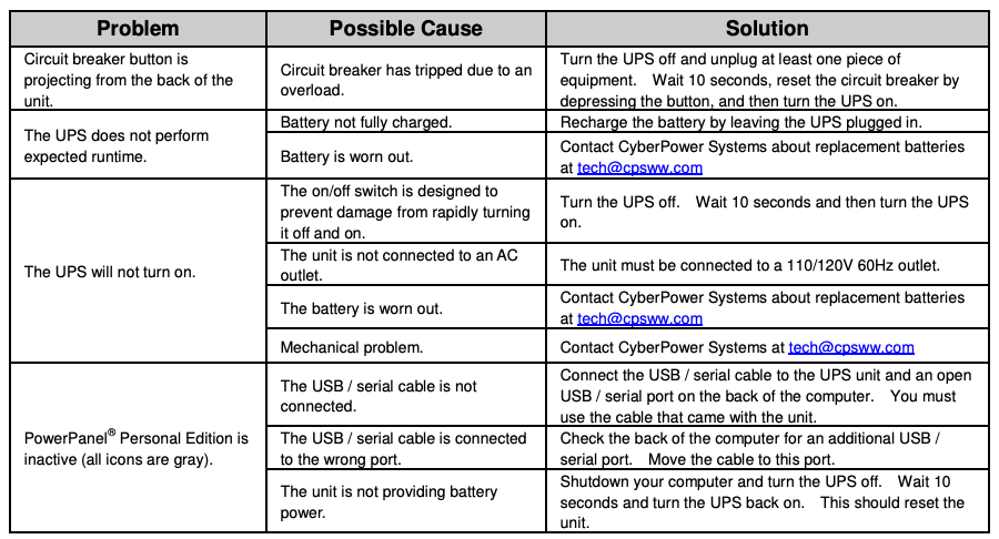
Additional troubleshooting information can be found under “Support” at www.cyberpower.com
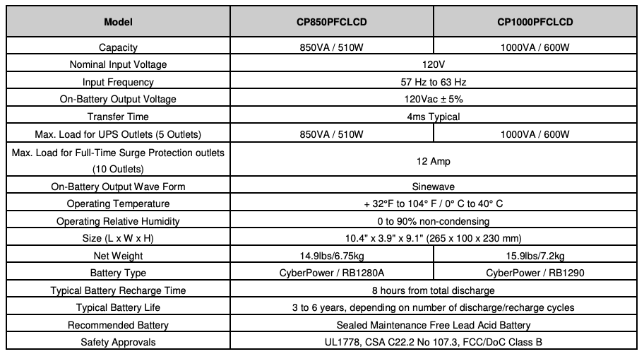
TECHNICAL SPECIFICATIONS
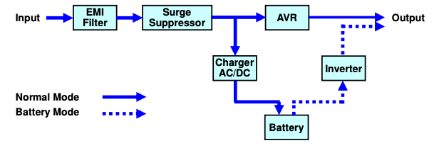
SYSTEM FUNCTIONAL BLOCK DIAGRAM
CYBERPOWER GREENPOWER UPS™ TECHNOLOGY
 Advanced Energy-Saving Patented Bypass Technology
CyberPower’s patented GreenPower UPS™ with Bypass Technology reduces UPS energy costs by up to 75% compared to conventional UPS models. Even when utility power is normal, conventional UPS models constantly pass power through a transformer. By contrast, under normal conditions the advanced circuitry of a GreenPower UPS™ bypasses the transformer. As a result, the power efficiency is significantly increased while decreasing waste heat, using less energy, and reducing energy costs.
When an abnormal power condition occurs, the GreenPower UPS™ automatically runs power through its transformer to regulate voltage and provide “safe” power. Since utility power is normal over 88% of the time, the GreenPower UPS™ operates primarily in its efficient bypass mode.
The GreenPower UPS™ is also manufactured in accordance with the Restriction on Hazardous Substances (RoHS) directive making it one of the most environmentally-friendly on the market today.
FCC Compliance Statement
FCC Compliance Statement
This device complies with part 15 of the FCC rules. Operation is subject to the following two conditions: (1) this device may not cause harmful interference, and (2) this device must accept any interference received, including interference that may cause undesired operation.
Note: This equipment has been tested and found to comply with the limits for a Class B digital device, pursuant to part 15 of the FCC Rules. These limits are designed to provide reasonable protection against harmful interference in a residential installation. This equipment generates, uses, and can radiate radio frequency energy and, if not installed and used in accordance with the instructions, may cause harmful interference to radio communications. However, there is no guarantee that interference will not occur in a particular installation. If this equipment does cause harmful interference to radio or television reception, which can be determined by turning the equipment off and on, the user is encouraged to try to correct the interference by one or more of the following measures:
- Reorient or relocate the receiving antenna.
- Increase the separation between the equipment and receiver.
- Connect the equipment to an outlet on a circuit different from that to which the receiver is connected.
- Consult the dealer or an experienced radio/TV technician for help”
Warning: Changes or modifications not expressly approved by the party responsible for compliance could void the user’s authority to operate the equipment.
Canadian Compliance Statement
CAN ICES-3 (B)/NMB-3(B)
References
[xyz-ips snippet=”download-snippet”]