![]()
YOUR ULTIMATE ALLY IN POWER
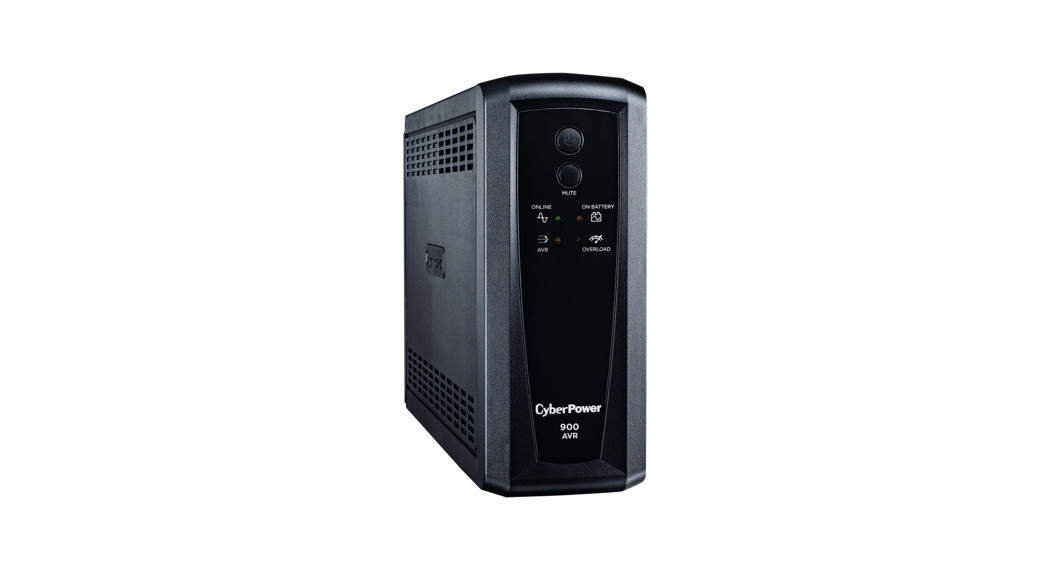
AVR UPS SERIESCP900AVR / CP1200AVR / CP1500AVRTUSER MANUAL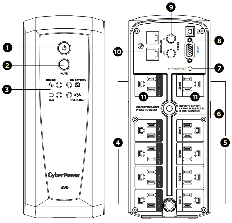
FEATURES
Power Switch
- MUTE Button
- LED Indicators
- Battery and Surge Protected Outlets
- Full-Time Surge Protection Outlets
- Circuit Breaker
- Wiring Fault Indicator (red)
- DB9/USB Ports to PC
- Coax/Cable/DSS Surge Protection
- Communication Protection Ports
- Widely-Spaced Outlets Designed for AC Adapters
PRODUCT REGISTRATION
Thank you for purchasing a CyberPower product. Please take a few minutes to register your product at: www.cyberpower.com/registration.Registration certifies your product’s warranty, confirms your ownership in the event of a product loss or theft, and entitles you to free technical support. Register your product now to receive the benefits of CyberPower ownership.
IMPORTANT SAFETY WARNINGS
(SAVE THESE INSTRUCTIONS)This Manual Contains Important Instructions that should be followed during the Installation and Maintenance of the UPS and batteries.
CAUTION! To prevent the risk of fire or electric shock, install in a temperature and humidity controlled indoor area free of conductive contaminants. (Please see specifications for the acceptable temperature and humidity range).CAUTION! To reduce the risk of electric shock, do not remove the cover except to service the battery. Turn off and unplug the unit before servicing the batteries. There are no user-serviceable parts inside except for the battery.CAUTION! Hazardous live parts inside can be energized by the battery even when the AC input power is disconnected.CAUTION! Not for use in a computer room as defined in the Standard for the Protection of Electronic Computer/Data Processing Equipment, ANSI/NFPA 75.CAUTION! The UPS must be connected to an AC power outlet with a fuse or circuit breaker protection. Do not plug into an outlet that is not grounded. If you need to de-energize this equipment, turn it off andunplug the unit.CAUTION! To avoid electric shock, turn off the unit and unplug it from the AC power source before servicing the battery.
CAUTION! To reduce the risk of fire, connect only to a circuit provided with 20 amperes maximum branch circuit overcurrent protection in accordance with the National Electric Code, ANSI/NFPA 70.DO NOT USE IT FOR MEDICAL OR LIFE SUPPORT EQUIPMENT! CyberPower Systems does not sell products for life support or medical applications. DO NOT use in any circumstance that would affectthe operation and safety of life support equipment, medical applications, or patient care.DO NOT USE WITH OR NEAR AQUARIUMS! To reduce the risk of fire or electric shock, do not use with or near an aquarium. Condensation from the aquarium can cause the unit to short out.DO NOT USE THE UPS ON ANY TRANSPORTATION! To reduce the risk of fire or electric shock, do not use the unit on any transportation such as airplanes or ships. The effect of shock or vibration caused during transit and the damp environment can cause the unit to short out.
INSTALLING YOUR UPS SYSTEM
INTRODUCTIONThank you for selecting a CyberPower Systems UPS product. This up is designed to provide unsurpassed power protection, operation, and performance during the lifetime of the product.UNPACKINGInspect the UPS upon receipt. The box should contain the following:(a) UPS(b) User’s manual(c) USB A+B type cable*PowerPanel® Personal software is available on our website. Please visit www.cyberpower.com and go to the Software Section for free download.
OVERVIEW
The CP900AVR/CP1200AVR/ CP1500AVRT provides complete power protection from utility power that is not always consistent. The CP900AVR/ CP1200AVR/CP1500AVRT features 1500 Joules of surge protection. The unit provides long-lasting battery backup during power outages with maintenance-free batteries. The CP900AVR/CP1200AVR/ CP1500AVRT ensures consistent power to your computer system and includes software that will automatically save your open files and shut down your computer system during a utility power loss.
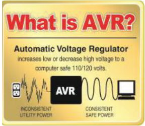
AUTOMATIC VOLTAGE REGULATOR
The CP900AVR/CP1200AVR/ CP1500AVRT stabilizes inconsistent utility power voltage to nominal levels that are safe for equipment. Inconsistent incoming utility power may be damaging to important data files and hardware, but with Automatic Voltage Regulation (AVR), damaging voltage levels are corrected to safe levels. AVR automatically- ly increases low utility power to a consistent and safe 110/120 volts.
 DETERMINE THE POWER REQUIREMENTS OF YOUR EQUIPMENT
- Ensure that the equipment plugged into the outlet does not exceed the UPS’s rated capacity (900VA/560W for CP900AVR, 1200VA/720W for CP1200AVR, and 1500VA/900W for CP1500AVRT). If the rated capacity of the unit is exceeded, an overload condition may occur and cause the UPS to shut down or the circuit breaker to trip.
- There are many factors that can affect the amount of power that your computer system will require. It is suggested that the load placed on the battery outlets not exceed 80% of the unit’s capacity.
INSTALLING YOUR UPS SYSTEM – ContinuedHARDWARE INSTALLATION GUIDE
- Your new UPS may be used immediately upon receipt. However, after receiving a new UPS, to ensure the battery’s maximum charge capacity, it is recommended that you charge the battery for at least 8 hours. Your UPS is equipped with an auto-charge feature. When the UPS is plugged into an AC outlet, the battery will automatically charge whether the UPS is turned on or off.
- Note: This up is designed with a safety feature to keep the system from being turned on during shipment. The first time you turn the UPS on, you will need o have it connected to AC power or it will not power up.

- With the UPS unit turned off and unplugged, connect your computer, monitor, and any other peripherals requiring battery backup into the battery power supplied outlets. DO NOT plug a laser printer, paper shredder, copier, space heater, vacuum, sump pump, or other large electrical devices into the “Battery and Surge Protected Outlets”. The power demands of these devices may overload and damage the UPS.
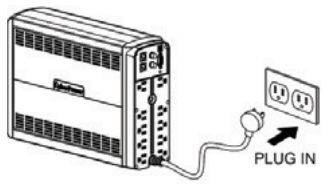
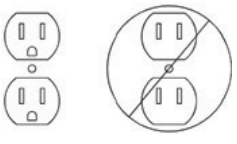
- Plug the UPS into a 2 pole, 3 wire grounded receptacle wall outlet). Make sure the wall branch outlet is protected by a fuse or circuit breaker and does not service equipment with large electrical demands (e.g. air conditioner, copier, etc…). The warranty prohibits the use of extension cords, outlet strips, and surge strips.
- Press the power switch to turn the unit on. The Power On indicator light will illuminate and the unit will “beep”. If an overload is detected, an audible alarm will sound and the unit will emit one long beep. To correct this, turn the UPS off and unplug at least one piece of equipment from the battery power supplied outlets. Make sure the circuit breaker is depressed and then turn the UPS on.
- To maintain optimal battery charge, leave the UPS plugged into an AC outlet at all times.
- To store the UPS for an extended period, cover it and store it with the battery fully charged. While in storage, recharge the battery every three months to ensure battery life.
- Ensure the wall outlet and UPS are located near the equipment being attached for proper accessibility. The warranty prohibits the use of extension cords, outlet strips, and surge strips in conjunction with the UPS unit.
BASIC OPERATION
- Power Switch Used as the master on/ off switch for equipment connected to the battery power supplied outlets.
- MUTE Button The button can be used to mute battery mode alerts and to set up the sensitivity. For more information, please refer to the” Function Setup Guide” section.• Pressing the button will turn off / on the battery mode alarm, including on battery / low battery warnings.• To turn the alarm off, press the MUTE button. You will hear two short beeps when the alarm is turned off.• To turn the alarm back on, press the MUTE button. You will hear a short beep when the alarm is turned on.
- LED Indicators The LEDs indicators show the UPS status, including On-Line / On Battery / AVR and Overload.
- Battery and Surge Protected OutletsThe UPS has five battery-powered/surge suppression outlets for connected equipment to ensure the temporary uninterrupted operation of your equipment during apower failure. (DO NOT plug a laser printer, paper shredder, copier, space heater, vacuum, sump pump, or other large electrical devices into the “Battery and Surge Protected Outlets”. The power demands of these devices may overload and damage the unit.)
- Full-Time Surge Protection Outlets The UPS has five surge suppression outlets.
- Circuit Breaker Located on the back of the UPS, the circuit breaker serves to provide overload and fault protection.
- Wiring Fault Indicator (red) This LED indicator will illuminate to warn the user that a wiring problem exists, such as bad ground, missing ground, or reversed wiring. If this is illuminated, disconnect all electrical equipment from the outlet and have an electrician verify the outlet is properly wired. The UPS will not provide surge protection without being plugged into a grounded and properly wired wall outlet. 8. USB Port to PC The USB communication port allows communication between the US B port on the computer and the UPS unit. DB9 Port This port is used for connecting between the UPS and equipment designedto operate with dry contact closure.
- Coax/Cable/DSS Surge Protection The Coax/Cable/DSS protection ports will protect any cable modem, CATV converter, or DSS receiver.
- communication Protection Ports, bi-directional, will protect a 10/100/1000 Ethernet connection (RJ45).
- Widely-Spaced Outlets Designed for AC Adapters The unit has two outlets spaced to allow AC power adapter blocks to be plugged into the UPS without blocking adjacent outlets.
REPLACING THE BATTERY
Replacement of batteries located in an OPERATOR ACCESS AREA
- When replacing batteries, replace with the same number of the following battery: CyberPower / RB1270X2C for the CP900AVR / CP1200AVR and CyberPower / RB1290X2 for CP1500AVRT.
- CAUTION! Risk of Energy Hazard, 24 V, maximum 7 Ampere-hour battery for CP900/1200AVR, maximum 9 Ampere-hour battery for CP1500AVRT. Before replacing batteries, remove conductive jewelry such as chains, wristwatches, and rings. High energy conducted through these materials could cause severeburns.
- CAUTION! Do not dispose of batteries in a fire. The batteries may explode
- CAUTION! Do not open or mutilate batteries. Released material is harmful to the skin and eyes. It may be toxic.
- CAUTION! A battery can present a risk of electrical shock and a high short circuit current. The following precautions should be observed when working onbatteries:1) Remove watches rings or other metal objects.2) Use tools with insulated handles.
CAUTION – RISK OF EXPLOSION IF BATTERY IS REPLACED BY AN INCORRECT TYPE. DISPOSE OF USED BATTERIES ACCORDING TO LOCAL REGULATIONSREMINDER: Batteries are considered HAZARDOUS WASTE and must be disposed of properly. Most retailers that sell lead-acid batteries collect used batteries for recycling, as required by local regulations.
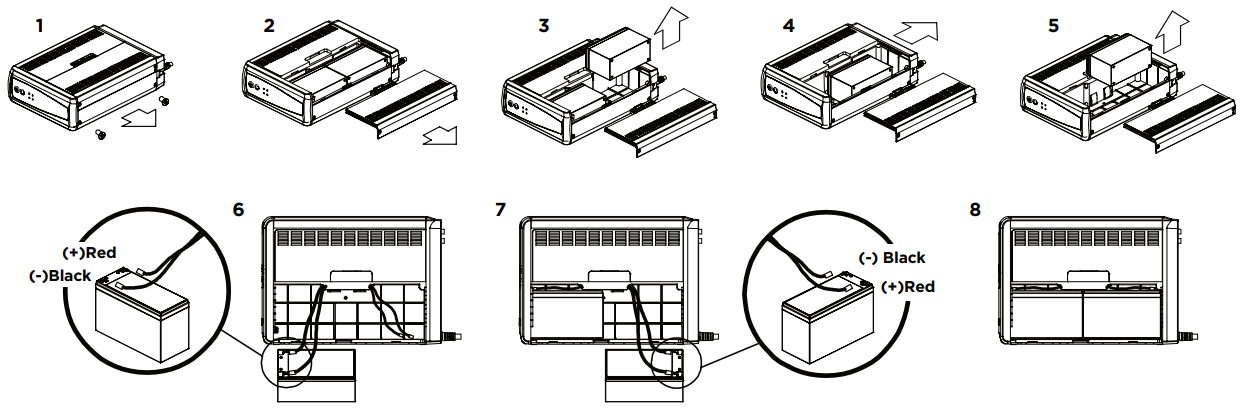
Yellow Wire to (+) Red Connector Black Wire to (-) Black ConnectorRed Wire to (+) Red Connector Yellow Wire to (-) Black Connector
BATTERY REPLACEMENT PROCEDURE
- Turn off and unplug all connected equipment.
- Turn the UPS off and unplug it from the AC power source.
- Turn the UPS on its side on a solid surface.
- Remove two retaining screws located on the bottom of the UPS.
- Press on the locking latch and slide the battery compartment cover.
- Disconnect the battery wires from the right side of the battery and then take them out of the battery compartment.
- Disconnect the battery wires from the remaining battery.
- Slide the remaining battery from left to right and remove it from the compartment.
- Install the “left side” replacement battery by connecting the yellow wire (+) to the red connector from the battery and the black wire (-) to the black connector from the battery. Place the battery into the left side of the compartment.
- Install the “right side” replacement battery by connecting the red wire (+) to the red connector from the battery and the yellow wire (-) to the black connector from the battery. Place the battery into the right side of the compartment. Note: Only new batteries should be used for replacement and both batteries should be replaced at the same time to ensure maximum life span.
- Close the battery compartment cover and tighten the retaining screws.
- Recharge the UPS for 8-16 hours to fully charge the battery.
DEFINITIONS FOR ILLUMINATED LED INDICATORS

On-Line |

On Battery |
 Overload Overload |
Condition | ||
| On | Off | Off | Off | Off | Normal |
| Off | Flashes whilebeeping | Off | Off | Beep twice every 30seconds | Utility Failure – The UPS is providing power to battery-protected outlets from its battery. |
| Off | Flashes whilebeeping | Off | Off | Rapid beeping EV second 1/2 s e | Utility Failure – The UPS is providing battery power. Rapid beeping indicates the unit will run out of power shortly. |
| 0- Of | Off/On | Off | On | Constant tone | Overload Fault – Occurs when connected equipment exceeds the listed capacity of the UPS. Turn the UPS off. unplug at least one piece of equipment from battery outlets. wait 10 seconds. reset the circuit breaker and turn the unit on. |
| On/Off | Off/On | Off | Off | Constant tone | Short Fault – Unplug at least one piece of equipment from battery outlets and turn the UPS on again.UPS Fault – Contact CyberPower Systems for support. |
| On/Off | Off/On | Off | Off | Beep every 2 seconds | Charger Fault – Contact CyberPower Systems for support. |
FUNCTION SETUP GUIDE – SENSITIVITY SETUP
Even when the UPS is operating normally (online mode), the AC input voltage may not be stable all the time. Sensitive equipment may be prone to damage caused by unexpected voltage fluctuations. Use the following steps to adjust the sensitivity of the UPS unit:
- Please make sure the UPS is in LINEMODE and operating in a normal condition.
- To Enter the Sensitivity Setup mode, press the MUTE Button for 6 seconds until all indicators flash rapidly.
- The unit will show the current sensitivity setting, as shown in the following table.
- To select the Low Sensitivity setting: shortly press the MUTE button until one red indicator flashes.
- To select the Medium Sensitivity setting, shortly press the MUTE button until red and yellow indicators flash.
- To select High Sensitivity setting, shortly press the MUTE button until green, yellow and red indicators flash.
- To set up a level of sensitivity, hold down the MUTE button until the green indicator (the first one) illuminates.
- Once in setup mode, if there is no action within 7 seconds, the unit will exit setup mode without changing any settings.
|
Indicators Illuminate |
Sensitivity |
Description |
| 1 (Red) | Low | If the connected equipment can tolerate more power events (for example: unstable power often associated with stormy weather), select Low Sensitivity, and the UPS will go to Battery Mode less often. |
| 2 (Yellow, Red) | Medium (Default) | The UPS will go to Battery Mode if the power is unstable. |
| 3 (Green, Yellow, Red) | High | If the connected equipment is more sensitive to power events, select High Sensitivity, and the UPS will go to Battery Mode more often. |
TROUBLESHOOTING
| problem | Possible Cause |
Solution |
| The circuit breaker button is projecting from the back of the unit. | The circuit breaker has been tripped due to an overload. | Turn the UPS off and unplug at least one piece of equipment. Wait 10 seconds, reset the circuit breaker by pressing the button, and then turn the UPS on. |
| The UPS does not perform the expected runtime. | The battery is not fully charged. | Recharge the battery by leaving the UPS plugged in. |
| The battery is worn out. | Contact CyberPower Systems about replacement batteries at: cyberpowersystems.com/support. | |
| The UPS will not turn on. | The on/off switch is designed to prevent damage from rapidly turning it off and on. | Turn the UPS off. Wait 10 seconds and then turn the UPS on. |
| The unit is not connected to an AC outlet. | The unit must be connected to a 120V 60Hz outlet. | |
| The battery is worn out. | Contact CyberPower Systems about replacement batteries at: cyberpowersystems.com/support. | |
| Mechanical problem. | Contact CyberPower Systems at: cyberpowersystems.com/support. | |
| PowerPanel® Personal is inactive (all icons are gray). | The USB /serial cable is not connected. | Connect the USB/serial cable to the UPS unit and an open USB /serial port on the back of the computer. You must use the cable that came with the unit. |
| The USB / serial cable is connected to the wrong port. | Check the back of the computer for an additional USB /serial port. Move the cable to this port. | |
| The unit is not providing battery power. | Shut down your computer and turn the UPS off. Wait 10 seconds and turn the UPS back on. This should reset the unit. |
Additional troubleshooting information can be found at “Support” at www.CyberPowerSystems.com
TECHNICAL SPECIFICATIONS
| Serin | CP900AVR | CP1200AVR | CP1500AVRT |
| Model | CP900AVR2 | CP1200AVR2 | CP1500AVRT2 |
| Capacity | 900VA / 560W | 1.200VA / 720W | 1.500VA / 900W |
| Nominal Input Voltage | 120V | ||
| Input Frequency | 60 Hz ± 3 Hz | ||
| On-Battery Output Voltage | 120 Vac ± 5% | ||
| Max. Load for UPS Outlets (5 Outlets) | 900VA / 560W | 1.200VA / 720W | 1.500VA / 900W |
| Max. Load for Full-Time Surge Protection outlets (10 Outlets) | 12 A | 12 A | 12.5 A |
| On-Battery Output Wave Form | Simulated Sine Wave | ||
| Operating Temperature | + 32°F to 104° F / 0° C to 40° C | ||
| Operating Relative Humidity | 0 to 95% non-condensing | ||
| Size (W x H x D) | 3.9″ x 9.8″ x 13.7″ (99 x 249 x 348 mm) | ||
| Net Weight | 21.83 lbs / 9.9 kg | 21.83 lbs / 9.9 kg | 24A lbs / 10.91 kg |
| Battery Type | CyberPower / RB127OX2C | CyberPower / RB127OX2C | CyberPower / RB1290X2 |
| Typical Battery Recharge Time | 8 hours to 90% capacity from total discharge | ||
| Typical Battery Life | 3 to 6 years. depending on the number of discharge/recharge cycles | ||
| Recommended Battery | Sealed Maintenance Free Lead Acid Battery | ||
| Safety Approvals | UL1778 (UPS). CSA C22.2 No. 107. FCC/DoC Class B |
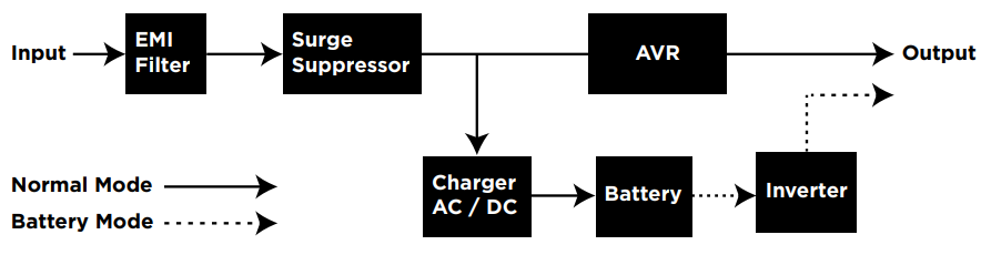
SYSTEM FUNCTION BLOCK DIAGRAM
CYBERPOWER GREEN POWER UPS™ TECHNOLOGY
CYBERPOWER GREENPOWER UPS™ TECHNOLOGYAdvanced Energy-Saving DesignThe GreenPower UPS™ has a high-efficiency charger, which makes it the most energy-efficient UPS in its class. The advanced high-frequency charging system significantly improves charging efficiency and conserves energy. As a result of this advanced design, the GreenPower UPS™ uses less energy compared to competitive models. The GreenPower UPS™ is manufactured in accordance with the Restriction on Hazardous Substances (RoHS) directive making it one of the most environmentally-friendly UPS systems on the market today.

FCC COMPLIANCE STATEMENT

This device complies with part 15 of the FCC rules. Operation is subject to the following two conditions:(1) this device may not cause harmful interference, and(2) this device must accept any interference received, including interference that may cause undesired operation.Note: This equipment has been tested and foundto comply with the limits for a Class B digital device, pursuant to part 15 of the FCC Rules. These limits are designed to provide reasonable protection against harmful interference in a residential installation. This equipment generates, uses, and can radiate radio frequency energy and, if not installed and used in accordance with the instructions, may cause harmful interference to radio communications. However, there is no guarantee that interference will not occur in a particular installation. If this equipment does cause harmful interference to radio or television reception, which can be determined by turning the equipment off nd on, the user is encouraged to try to correct the interference by one or more of the following measures:
- Reorient or relocate the receiving antenna.
- Increase the separation between the equipment and receiver.
- Connect the equipment to an outlet on a circuit different from that to which the receiver is connected.
- Consult the dealer or an experienced radio/TV technician for help.
Warning: Changes or modifications not expressly approved by the party responsible for compliance could void the user’s authority to operate the equipment.
Canadian Compliance StatementCAN ICES-3 (B)/NMB-3(B)
LIMITED WARRANTY AND CONNECTED EQUIPMENT GUARANTEE
Please visit www.CyberPowerSystems.com for a copy of the Limited Warranty and Connected Equipment Guarantee.
Where Can I Get More Information?The application of the United Nations Convention of Contracts for the International Sale of Goods is expressly excluded. CyberPower is the warrantor under this Limited Warranty. For further information please feel free to contact CyberPower at:Cyber Power Systems (USA), Inc.4241 12th Ave E., STE 400Shakopee, MN 55379call us at (877) 297-6937; or submit a web ticket online at:cyberpowersystems.com/support.
Cyber Power Systems (USA), Inc. encourages environmentally sound methods for the disposal and recycling of its UPS products. Please dispose and/or recycle your UPS and batteries in accordance with the local regulations of your state.WARNING: This product can expose you to chemicals including bisphenol A (BPA) andstyrene, which is known to the State of California to cause reproductive harm and cancer. For more information, go to www.P65Warnings.ca.gov.© 2021 CyberPower Systems (USA), Inc. PowerPanel® Personal is a trademark of Cyber Power Systems(USA) Inc. All rights reserved. All other trademarks are the property of their respective owner
References
[xyz-ips snippet=”download-snippet”]