CYPRESS OSM-1000-BRD OSDP-Wiegand Converter User Guide
Product Overview
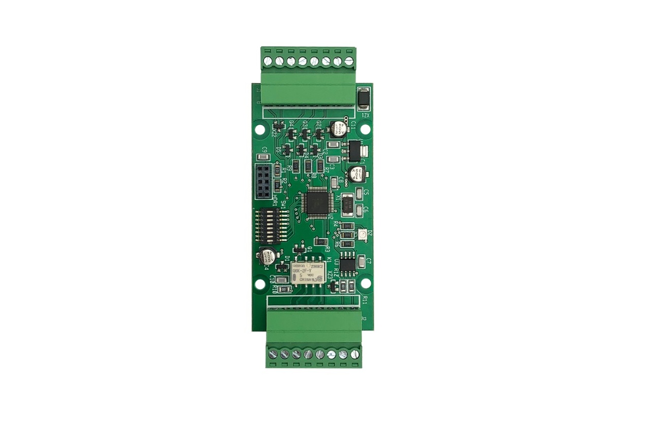
The OSM-1000-BRD (board only) OSDP-Wiegand Converter is a general purpose Wiegand / OSDP converter. The OSM unit has two operating modes, PD (Peripheral Device) mode and ACU (Access Control Unit) mode. In PD mode, the OSM unit connects a traditional Wiegand reader to an OSDP ACU. In ACU mode, the OSM unit connects an OSDP reader to a traditional Wiegand Access Controller. Additionally, two OSM-1000 units can be used together, one in ACU mode and the other in PD mode, to connect a Wiegand reader to a Wiegand Access Controller with an OSDP connection in between. The OSM-1000 meets OSDP Verified conformance testing.
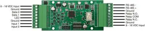
Pin Designations
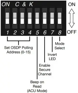
DIP Switch Settings
- DIP Switches 1-4: Set the OSDP Polling Address in PD mode. Set the OSDP Address to be polled by the OSM unit in ACU mode. See the DIP Switch Address Table to the right.
- DIP Switch 5: When ON, enables the Beep on Read feature when in ACU mode.
- DIP Switch 6: When ON, OSM-1000 will only establish Secure Channel communication sessions.
- DIP Switch 7: When ON, inverts osdp_LED command sent to PD when in ACU mode; and inverts the state of the output pin based on osdp_LED command received in PD mode.
- DIP Switch 8: When ON, the OSM-1000 is set to ACU mode. When OFF, the OSM-1000 is set to PD mode.

|
DIP Switch Address Table |
||||
|
1 |
2 | 3 | 4 | Address # |
|
Address 0 |
||||
| X |
Address 1 |
|||
| X | Address 2 | |||
| X | X |
Address 3 |
||
| X | Address 4 | |||
| X | X |
Address 5 |
||
| X | X | Address 6 | ||
| X | X | X |
Address 7 |
|
| X | Address 8 | |||
| X | X |
Address 9 |
||
| X | X | Address 10 | ||
| X | X | X |
Address 11 |
|
| X | X | Address 12 | ||
| X | X | X |
Address 13 |
|
| X | X | X | Address 14 | |
| X | X | X | X |
Address 15 |
|
X = ON |
OSDP Default Parameters
Secure Channel Base Key (SCBK): 303132333435363738393A3B3C3D3E3F
- Polling Address: 0
- Baud Rate: 9600
OSDP Communication Failure
How the OSM-1000 reacts when OSDP communication fails.
- ACU Mode: When the OSM-1000 established communication with a PD the Relay will be activated (continuity between Relay COM and Relay N.O.). If the communication fails and the PD does not respond within 10 polls the Relay will be deactivated (continuity between Relay COM and Relay N.C.).
- PD Mode: If communication fails between the OSM-1000 and the ACU, the status LED on OSM-1000 will slowly fade from red to off, and back to red.
For more detailed information on the OSM-1000 visit CypressIntegration.com
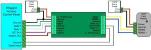
ACU Mode Wiring Diagram
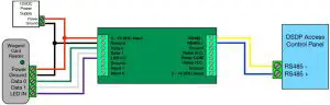
PD Mode Wiring Diagram
Status LED Behavior
The OSM-1000-BRD unit has a tri-color LED that can display red, green, blue, and white. The startup sequence lasts approximately 5 seconds and the LED will display red, blue, green, white or display red, green, blue, white.
ACU Mode
- OSM-1000 is communicating with PD: the status LED will be blue with green flashes or green with blue flashes. The status LED will briefly turn red when it receives reader data from the PD.
- OSM-1000 is not communicating with PD: the status LED will be blue with slow, green flashes or green with slow, blue flashes.
PD Mode
- OSM-1000 is communicating with ACU: the status LED will be red with blue flashes or red with green flashes.
- OSM-1000 has not been polled by the ACU: the status LED will slowly fade from green to off, and back to green.
- ACU stops communicating with OSM-1000: the status LED will slowly fade from red to off, and back to red.
Bench Testing
Bench testing is recommended to avoid troubleshooting issues in the field.
ACU Mode
- At the bench, connect the OSM unit to the PD and the Wiegand access controller by following the ACU Mode Wiring Diagram.
- Observe the OSM unit and PD communicating. Refer to the “Status LED Behavior” section to verify that the OSM unit is communicating with the PD.
- If the devices do not communicate, make sure the the baud rate and polling ID match. In the OSDP spec, the default baud rate is 9600 and the default polling ID is 0.
PD Mode
- At the bench, connect the OSM unit to the Wiegand reader and ACU by following the PD Mode Wiring Diagram.
- Observe the OSM unit and ACU communicating. Refer to the “Status LED Behavior” section to verify that the OSM unit is communicating with the ACU.
- If the devices do not communicate, make sure the the baud rate and polling ID match. In the OSDP spec, the default baud rate is 9600 and the default polling ID is 0.
References
[xyz-ips snippet=”download-snippet”]