![]()
Vigilance Outdoor Bullet CameraDCS-4712E, DCS-4714E, DCS-4718EQUICK INSTALLATION GUIDE
Before You Begin
This installation guide provides instructions for installing and configuring your camera. Additional documentation is also available on the D-Link support website.Refer to the manual for your model for additional information on how to configure the device using the associated Setup Wizard.The manual and Setup Wizard may be found at https://dlink.com/support/.
Package Contents
This package includes the following items:
- Vigilance Outdoor Bullet Camera
- Cable Waterproofing Connector
- Mounting Kit
- Allen Key
- Alignment Sticker
- Documentation
If any of the above items are damaged or missing, please contact your local D-Link reseller.Note: Using a power supply with a different voltage than the one recommended for the device will cause damage and void the warranty for this product.
System Requirements
- Computer running Microsoft Windows®
- Internet Explorer 11
Hardware Overview
DCS-4712E/DCS-4714E Front
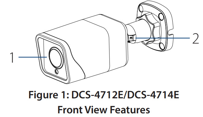
| # | Feature | Description |
| 1 | Camera Lens | Fixed camera lens. |
| 2 | Adjustable Mount | Loosen the screw with the included Allen key to adjust the camera angle. Tighten it to lock the camera angle. |
Table 1: DCS-4712E/DCS-4714EFront View Descriptions
DCS-4718E Front
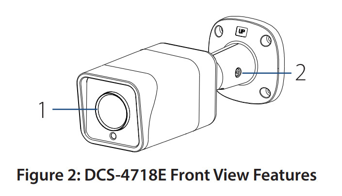
| # | Feature | Description |
| 1 | Camera Lens | Motorized varifocal lens. |
| 2 | Adjustable Mount | Loosen the screw with the included Allen key to adjust the camera angle. Tighten it to lock the camera angle. |
Table 2: DCS-4718E Front View Descriptions
Cable Interfaces
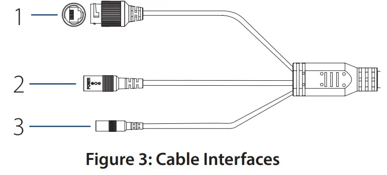
| # | Feature | Description |
| 1 | EthernetJack | RJ-45 connector for Ethernet. Can also, be used to power the camera using Power over Ethernet (PoE) |
| 2 | PowerConnector | Connects to an optional 12 V / 1.5 A power adapter (not included) |
| 3 | ResetButton | Press and hold for more than five seconds, then release to perform a factory reset. |
Table 3: Cable Interface Descriptions
DCS-4712E/DCS-4714E Rear Panel Interfaces
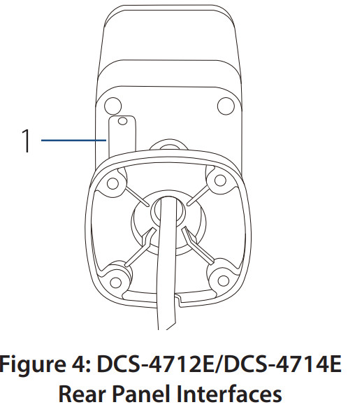
| # | Feature | Description |
| 1 | microSD Slot | Slot for a microSD card. |
Table 4: DCS-4712E/DCS-4714E Rear Panel Interface DescriptionsDCS-4718E Bottom Panel Interfaces
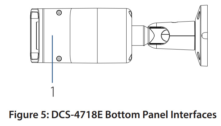
| # | Feature | Description |
| 1 | microSD Slot | Slot for a microSD card. |
Table 5: DCS-4718E Bottom Panel Interface Descriptions
Management Options
To configure and manage your camera, it is recommended that you download the associated Setup Wizard and the D-ViewCam software suite, both of which are available fromthe D-Link website.
Installing the Setup Wizard
- Open a web browser, navigate to dlink.com/support/, and select your region.
- On the next screen, enter the model number of your camera in the search bar and click Search. Click the picture of your camera. On the product page, click the Download button next to Setup Wizard.
- Once the executable file has finished downloading, click it and follow the instructions to install the Setup Wizard.
Configuring the Camera
- Ensure that your camera is plugged in (either using a 12 V 1.5 A power adapter or a PoE-enabled device) and connected to your computer with an Ethernet cable.
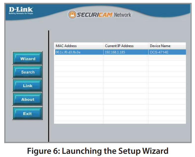
- Open the Setup Wizard. It will display the MAC address and IP address of your camera. If you have a DHCP server on your network, this will be a dynamic IP address. If your network does not use a DHCP server, the network camera’s default IP address 192.168.0.20 will be displayed. Select your camera, then click the Link button to continue.

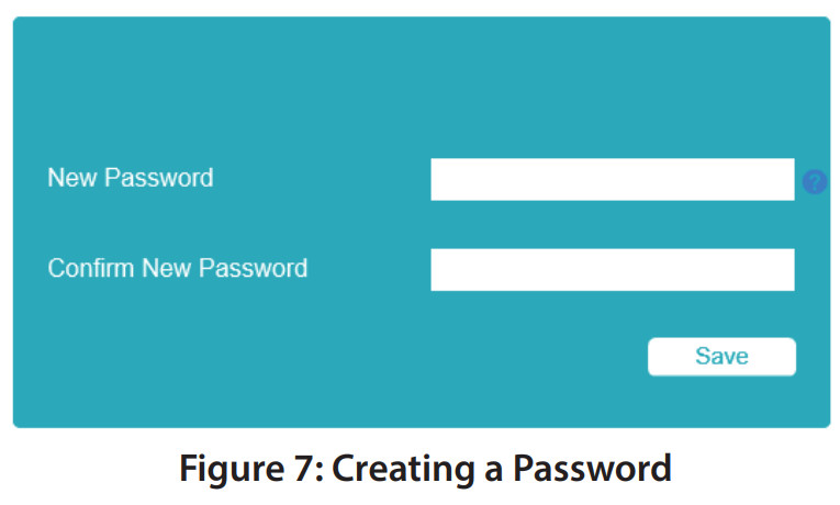
- If this is your first time logging in, you will be prompted to create a password, which must be between 8 and 30 characters and must contain both letters and numbers. Press Save.
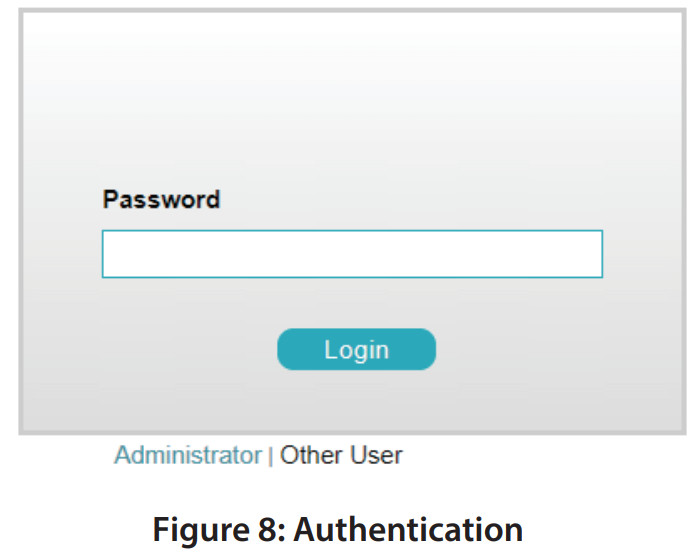
- To view the camera display, click the Search button on the main screen of the Setup Wizard, then select your camera and click the Link button to open the camera’s web UI. Alternatively, open a web browser and type the camera’s IP address (displayed in step 2) into the address bar, and press Enter. Enter the newly created password, and click on ogin to continue.
Installing D-ViewCam
- Open a web browser, navigate to dlink.com/support/, and select your region.
- On the next screen, click the D-ViewCam link and click the most recent version to download the D-ViewCam setup wizard (packaged as a zip file).
- Once the file has finished downloading, unzip it, and click the executable file SetupTool.exe. Follow the instructions to install the D-ViewCam software suite.
For advanced viewing options, refer to the D-ViewCam User Manual.
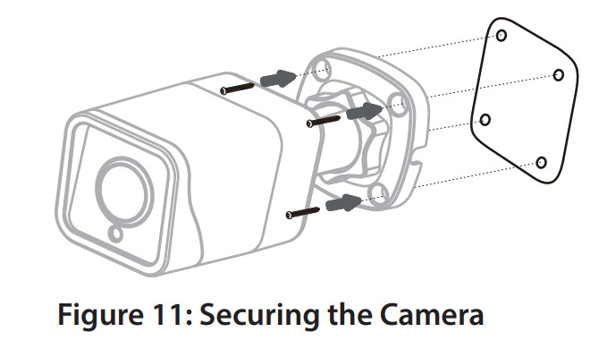
Mounting the Camera
Note: It is highly recommended that you configure and test your camera before mounting it. If you plan on inserting a microSD card, it is also recommended to do this before mounting.
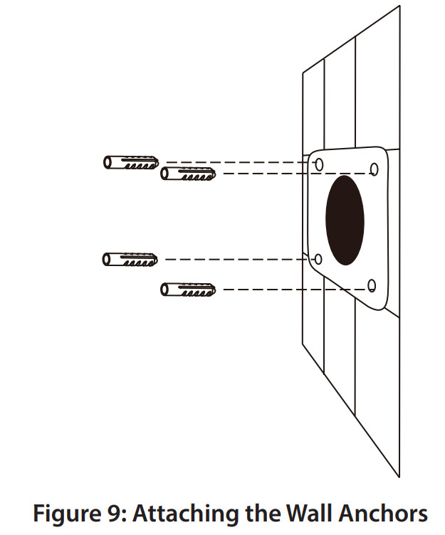
- Place the alignment sticker where you want to position the camera. Make sure the camera base will be positioned so that the cable channel is on the bottom.
- Use a 4 mm drill bit to make the required holes approximately 30 mm deep, then insert the wall anchors into the holes.
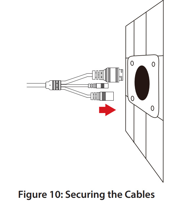
- If you are running the camera cables through the wall, drill a hole in the center and pull the cables through the hole. If you are running the camera cables out the side of the camera, guide the camera cables through the cable channel on the base.
- Use the screws provided to mount the camera to the wall.
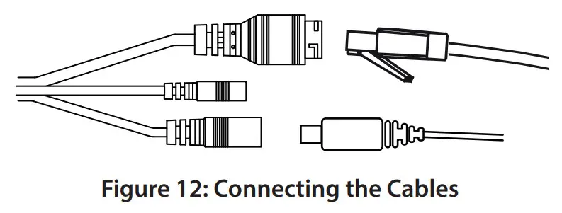
- Connect the power and Ethernet cables, or just the Ethernet cable if you are using a PoE connection.
- To adjust the camera’s monitoring direction, use the Allen key to turn the adjustment screw counterclockwise to loosen it, then move the camera to the desired position and angle. When you are finished, turn the adjustment screw clockwise to tighten it.
Waterproofing Your Installation
A round Ethernet cable, a crimping tool, and RJ-45 plugs are required for this procedure.
- Place the washer around the base of the Ethernet connector as shown.
- Thread the bare Ethernet cable through the waterproof connector as shown.
- Attach an RJ-45 plug to the end of the cable using a crimping tool.
- Connect the RJ-45 plug into the Ethernet connector, then screw the waterproof connector to the Ethernet connector by turning it clockwise about one half-turnFigure 16: Attaching the Waterproof Connector
- Screw the back part of the waterproof connector clockwise until there is a tight seal around the Ethernet cable.
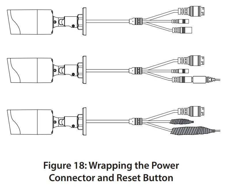
- The power connector and reset button cables are not waterproof. It is recommended to use waterproof tape to protect them. Wind the tape around each cable in an overlapping manner to cover them.

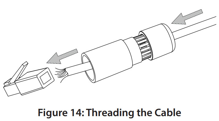

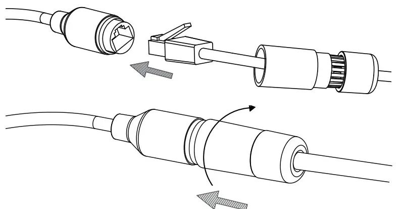 Figure 16: Attaching the Waterproof Connector
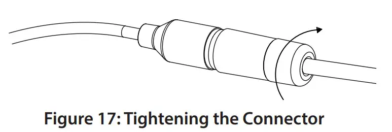
Additional Information
If you are encountering problems setting up your network, please refer to the user manual. Additional help is available online. To find out more about D-Link products or marketing information, please visit the D-Link support website at http://dlink.com/support/.
Warranty Information
Please visit http://warranty.dlink.com/ for warranty information for your region.
TECHNICAL SUPPORTdlink.com/support

References
[xyz-ips snippet=”download-snippet”]