Quick Installation GuideDES-1009MP
Before You Begin
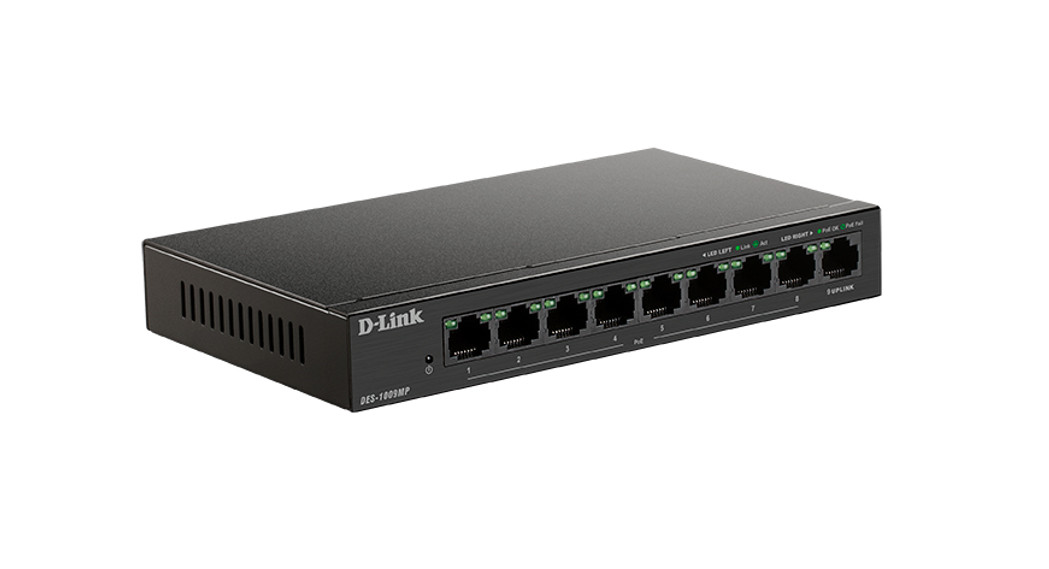
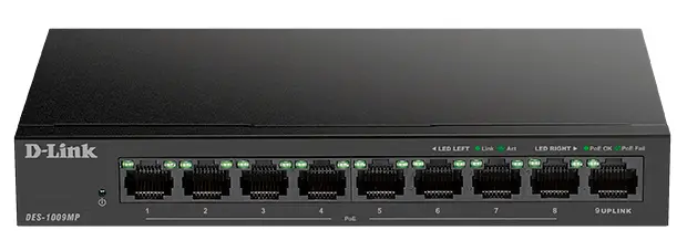
This Quick Installation Guide gives you step-by-step instructions for setting up your DES-1009MP 9-port 10/100 PoE Switch. The model you have purchased may appear slightly different from the one shown in the illustrations.
Package Contents
This DES-1009MP package should include the following items:
- 1 x DES-1009MP
- 1 x Power adaptor
- 1 x Quick Installation Guide
If any of the above items are damaged or missing, please contact your local D-Link reseller.
Hardware Overview
LED Indicators
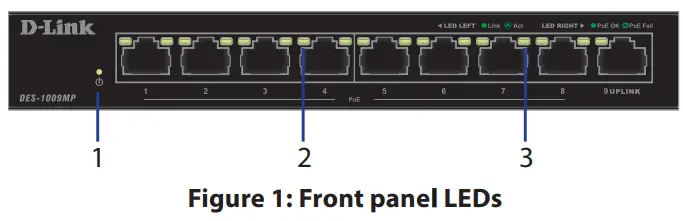
| # | LED | Status | Description |
| 1 | Power | Solid green | The switch is powered on. |
| Off | The switch is turned off. | ||
| 2 | Link/AmSpeed(LeftLed) | Solid green | There is an active link negotiated on this port. |
| Blinking green | There is traffic at the port. | ||
| Off | There is no active link on this port. | ||
| 3 | PoE(RightLed) | Solid green | The port is providing power to the connected PoE-powered device. |
| Blinking green | This indicates a PoE-powered device is connected to this PoE port, but the switch has insufficient remaining power budget to power the device. | ||
| Off | There is no PoE-powered device connected to this port. |
Table 1: LED overview
Front Panel Connectors
| # | Interface | Description |
| 1 | Ports 1 -8 | 10/100 Mbps PoE-capable ports, used for connecting Ethernet devices and PoE-powered devices. |
| 2 | Ports 9 | 10/100/1000 Mbps Ethernet port for uplink connections to NVR, storage, or core switch. |
Table 2: Front connector description
Rear Panel Connectors
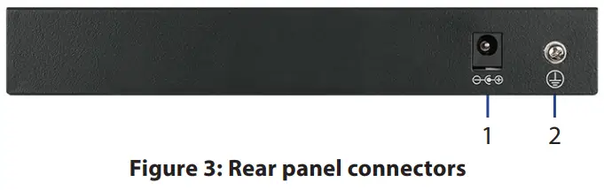
| # | Connector | Description |
| I | DC Power Input | Input jack for the power adapter. |
| 2 | SWITCH GND | The screw is used to secure a grounding wire to connect the switch to the ground. |
Table 3: Rear connector description
Hardware Installation
Installation Precautions
For safe switch installation and operation, it is recommended to:
- Visually inspect the DC power jack and make sure that it is fully secured to the power adapter.
- Make sure that there is proper heat dissipation and adequate ventilation around the switch.
- Install the switch in a site free from strong electromagnetic sources, vibration, dust, and direct sunlight.
- Not place heavy objects on the switch.
Grounding the Switch
The following steps explain the procedure for connecting the switch to a protective ground:
- Verify that the system is powered off.
- Remove the ground screw and place the #8 terminal lug ring at one end of the ground cable on top of the ground screw opening.
- Insert the ground screw back into the ground screw opening.
- Using a screwdriver, tighten the ground screw to secure the ground cable to the switch.
- Attach the terminal lug ring at the other end of the grounding cable to an appropriate grounding source.
- Verify that the connections from the ground connector on the switch to the grounding source are securely attached.
Powering On the Switch
After connecting the switch to the network using a compatible category 5/6/7 UTP network cable, simply connect the switch to a power outlet to power the device.

TECHNICAL SUPPORT dlink.com/support
[xyz-ips snippet=”download-snippet”]