![]()
D-Link DGS-1008P 8Port Gigabit Switch Installation Guide
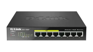
DGS-1008P
This document will guide you through the basic installation process for your new D-Link Unmanaged Switch.
Before You Begin
This Quick Installation Guide gives you step-by step instructions for setting up your DGS-1008P 8-port Gigabit PoE Desktop Switch. The model you have purchased may appear slightly different from the one shown in the illustrations. For more detailed information about the switch and technical specifications, please refer to the User Manual.
Package Contents
This DGS-1008P package should include the following items:
- 1 x DGS-1008P
- 1 x AC to DC power adapter with power cord
- 1 x Wall mounting kit
- 1 x Quick Installation Guide
If any of the above items are damaged or missing, please contact your local D-Link reseller.
Hardware Overview
LED Indicators
Figure 2: Front panel connectors
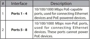
Table 2: Front connector description
Rear Panel Connectors
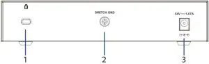
Figure 3: Rear panel connectors
Hardware Installation
Installation Precautions
For safe switch installation and operation, it is recommended to:
- Visually inspect the DC power jack and make sure that it is fully secured to the power adapter.
- Make sure that there is proper heat dissipation and adequate ventilation around the switch.
- Install the switch in a site free from strong electromagnetic sources, vibration, dust, and direct sunlight.
- Not place heavy objects on the switch.
Grounding the Switch
The following steps explain the procedure for connecting the switch to a protective ground:
- Verify that the system is powered off.
- Remove the ground screw and place the #8 terminal lug ring at one end of the ground cable on top of the ground screw opening.
- Insert the ground screw back into the ground screw opening.
- Using a screwdriver, tighten the ground screw to secure the ground cable to the switch.
- Attach the terminal lug ring at the other end of the grounding cable to an appropriate grounding source.
- Verify that the connections from the ground connector on the switch to the grounding source are securely attached.
Attaching the Rubber Pads
The DGS-1008P comes with a strip with 4 adhesive rubber pads to place on the bottom of the device to prevent the switch from damaging the surface it is placed on. To attach the rubber pads, simply remove the rubber pads from the adhesive strip and stick one pad on each corner on the bottom panel of the switch.
Mounting the Switch to a Wall
The DGS-1008P can also be mounted to a wall for more convenient placement. Follow the instructions below for more information on how to mount the device to different types of walls.
Hard surface wall (e.g. cement, brick)
- Drill two holes that align with the keyholes on the back of the switch in the wall where you want to mount the DGS-1008P and place the two included nylon screw anchors into the drilled holes.
- Drive the two screws included in this package into the placed nylon anchors.
- Hook the mounting keyholes on the back of the switch onto the screws to secure the device to the wall.
Soft surface wall (e.g. wood, drywall)
- Drive the two screws included in this package into the soft surface wall where you want to mount the DGS-1008P so that they align with the keyholes on the back of the switch.2. Hook the mounting keyholes on the back of the switch onto the screws to secure the device to the wall.
Powering On the SwitchAfter connecting the switch to the network using a compatible category 5/6/7 UTP network cable, simply connect the switch to a power outlet to power the device.

SUPORT TEHNIC: dlink.com/support
References
[xyz-ips snippet=”download-snippet”]