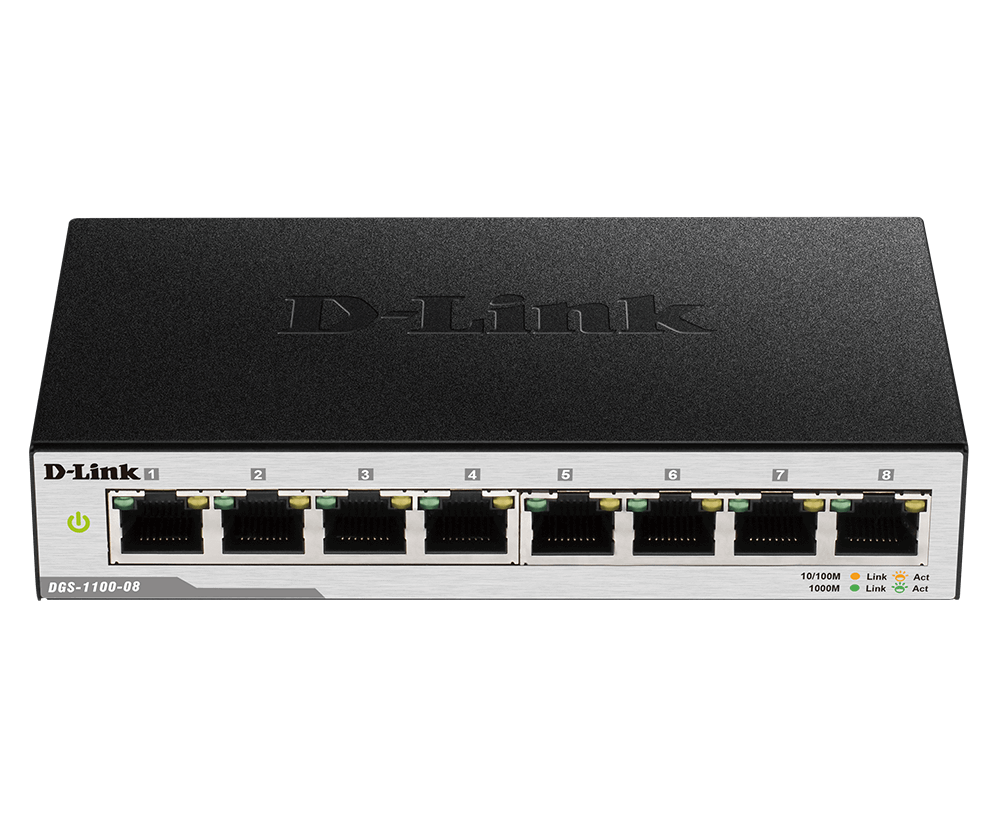
D-Link DGS-1100-05PD 5-Port gigabit Smart Managed Switch and PoE Extender

About This Guide
This guide gives step-by-step instructions for setting up the D-Link DGS-1100-05PD switch. Please note that the model you have purchased may appear slightly different from those shown in the illustrations.
Step 1 – Unpacking
Open the shipping carton and carefully unpack its contents. Please consult the packing list to make sure all items are present and undamaged. If any item is missing or damaged, please contact your local D-Link reseller for replacement.
- DGS-1100-05PD switch
- Wall mounting kit
- 4 rubber feet
- Quick Installation Guide
Step 2 – Switch Installation
For safe switch installation and operation, it is recommended that you:
- Make sure that there is proper heat dissipation and adequate ventilation around the switch.
- Do not place heavy objects on the switch.
Desktop or Shelf Installation
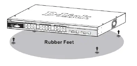
When installing the switch on a desktop or shelf, the rubber feet included with the device must be attached on the bottom at each corner of the device’s base. Allow enough ventilation space between the device and the objects around it.

Wall Mount Installation
The switch can also be mounted on a wall. Two mounting slots are provided on the bottom of the switch for this purpose.
Mounting on a concrete wall
- Fix the nylon screw anchors into the concrete wall.
- Drive the T3 x 15L screws into the nylon screw anchors.
- Hook the switch with the mounting holes on the bottom onto the screws.
Mounting on a wooden wall
- Drive the T3 x 15L screws into the wooden wall.
- Hook the switch with the mounting holes on the bottom onto the screws.

Grounding the Switch
This step must be completed before powering on the switch. Required tools and equipment for grounding
- Grounding screw (included) and one M4x6 (metric) pan-head screw (not included).
- Grounding cable (not included). The grounding cable should be sized according to local and national installation requirements. Depending on the power supply and system, a 12 to 6 AWG copper conductor is required for installation. Commercially available 6 AWG wire is recommended. The length of the cable depends on the proximity of the switch to proper grounding facilities.
A screwdriver (not included).
- Verify that the system is powered off
- Remove the grounding screw from the back of the device and place the #8 terminal lug ring of the grounding cable on top of the grounding screw opening.
- Insert the grounding screw back into the screw opening and use a screwdriver to tighten the grounding screw.
- Attach the terminal lug ring at the other end of the grounding cable to an appropriate grounding source.
- Verify that the connection between the grounding connector on the switch and the grounding source is secure.
Step 3. Power Connection
The DGS-1100-05PD switch is powered via Ethernet cable (Power over Ethernet (PoE)) 802.af/at through the port 5 (PD port) only. Connect Ethernet cable from a feeding device to the port 5 on the DGS-1100-05PD.
Management Options
This switch can be managed through the Web User Interface (Web UI) or D-Link Network Assistant (DNA) utility. If you wish to manage a single D-Link switch, the Web UI may be the best option. Each switch must be assigned its own IP address, which is used for communication with the management PC. However, if you wish to manage multiple D-Link switches, DNA may be the best option. You don’t need to change the IP address of your PC and it makes the initial setup of multiple switches easy. Please refer to the following installation instructions to get started with the Web UI and DNA.
Web User Interface
After a successful physical installation, you can configure the Switch, monitor the LED panel, and display statistics graphically using a web browser, such as Microsoft Internet Explorer (version 7 and higher), Firefox, Chrome and Safari. The equipment you need to begin the web configuration of your device:
- A PC with a RJ-45 Ethernet connection
- A standard Ethernet cable
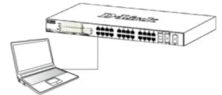
- Connect the Ethernet cable to any of the ports in front panel of the switch and to the Ethernet port on the PC.

- Configure the PC’s IP address to be in the network segment as the switch. The switch’s default IP address is 10.90.90.90 , with subnet mask 255.0.0.0 . For example, to connect to the switch using the default settings, your PC should have an IP address in the range: 10.0-255.0-255.1-254 and a subnet mask of 255.0.0.0.
- Open the web browser and enter http://10.90.90.90/ in the address box.Note: The Web UI can also be accessed through DNA, by clicking IP in the device list.
- Log in to the switch. When the authentication window appears, enter the password ‘admin’. Press OK to enter the main configuration window.
D-Link Network Assistant
D-Link Network Assistant (DNA) is a program that is used to discover switches which are in the same Layer 2 network segment as your PC. You can download the DNA App from the Chrome Web Store and install it in a Chrome web browser.
- Go to the Chrome web store and search for ‘D-Link Network Assistant’ to download the App. This can be reached at the following URL: https://chrome.google.com/webstore
- Click ‘ADD TO CHROME’ button on the right hand side of the search results.
- Click ‘Add app’ button in the pop up window to install the D-Link Network Assistant in Chrome.
- When the installation process completes: (Option 1) Click the ‘LAUNCH APP’ button in the upper-right corner of the window to start DNA.
(Option 2) Click the ‘Apps’ icon in the upper-left corner of the Chrome browser and click ‘DNA’ in the Apps list to start DNA.
Note: for managed switches, users need to enable D-Link Discovery Protocol (DDP) and create a user name and password to be able to log in to DNA.
Additional Information
Also you can download the DNA App from the D-link website at http://www.dlink.ru/ru/products/1/ in the “Download” site section of the switch model you have purchased.
References
[xyz-ips snippet=”download-snippet”]


