D-Link DGS-3000-28LP Gigabit L2 Managed Switches Installation Guide
Package Contents
Open the shipping carton of the Switch and carefully unpack its contents. The carton should contain the following items:
- One DGS-3000-28LP switch
- One AC power cord
- One console cable (RJ-45 to RS-232)
- One rack mounting kit (two brackets and screws)
- Four rubber feet with adhesive backing
- One power cord retainer set
- One Quick Installation Guide
Installation Guidelines
This section will discuss the hardware installation guidelines that the user must follow in order to properly and safely install this switch into the appropriate environment.
- Visually inspect the power cord and see that it is fully secured to both the power connector, on the Switch, and the electrical outlet that supplies power.
- Install the Switch in a fairly cool and dry place within the acceptable operating temperature and humidity ranges.
- Install the Switch in a site free from strong electromagnetic field generators such as motors, vibration, dust, and direct exposure to sunlight.
Installing the Switch without a Rack
This section is used to guide the user through installing the Switch in an area other than a switch rack. Attach the included rubber feet to the bottom of the Switch. Take note that there should be marked blocks on the bottom of the Switch to indicate where to attach the rubber feet. These markings are usually found in each corner on the bottom of the device. The rubber feet cushion the Switch, protecting the casing from scratches and preventing it from scratching other surfaces.
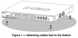
Install the Switch on a sturdy, level surface that can support the weight of the Switch. Do not place any heavy objects on the Switch. The power outlet should be within 1.82 meters (6 feet) of the Switch. Make sure that there is proper heat dissipation from and adequate ventilation around the Switch. Leave at least 10 cm (4 inches) of space at the front, sides, and rear of the Switch for ventilation.
Installing the Switch in a Standard 19” Rack
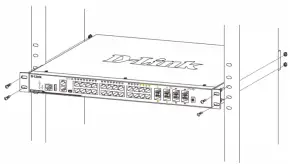
This section is used to guide the user through installing the Switch into a switch rack. The Switch can be mounted in a standard 19″(1U) rack using the provided mounting brackets. Fasten the mounting brackets to the sides of the Switch using the screws provided.
Fasten the mounting brackets in any available open space in the rack using the screws provided.
Installing Transceivers into the Transceiver Ports
The Switch is equipped with Small Form-factor Pluggable (SFP) ports that can be used to connect various other networking devices to this switch that do not support the standard RJ-45 wiring connection. These ports are generally used to connect this switch to optical fiber connections and can be used to connect devices to the Switch over great distances. The maximum distance that the RJ-45 wiring connection can reach is 100 meters. Fiber optic connections can span several kilometers.
 Figure 4 — Inserting transceivers into the transceiver ports
Power On (AC Power)
Plug one end of the AC power cord into the power socket of the Switch and the other end into the local power source outlet. After the system is powered on, the LED will blink green to indicate that the system is booting up.
Power Failure (AC Power)In the event of a power failure, just as a precaution, unplug the power cord from the Switch. After the power returns, plug the power cord back into the power socket of the Switch.
Installing Power Cord Retainer
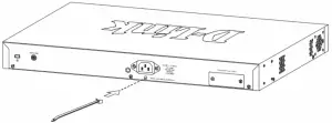 Figure 5 — Insert Tie Wrap into the SwitchTo prevent accidental removal of the AC power cord, it is recommended to install the power cord retainer together with the power cord.
With the rough side facing down, insert the tie wrap into the hole below the power socket.
Plug the AC power cord into the power socket of the Switch.
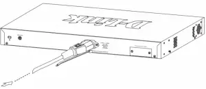 Figure 6 — Connect the power cord to the Switch
Slide the retainer through the tie wrap until the end of the cord.
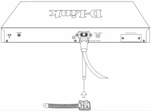 Figure 7 — Slide the Retainer through the Tie Wrap
Circle the tie of the retainer around the power cord and into the locker of the retainer.
Figure 8 — Circle around the power cord
Fasten the tie of the retainer until the power cord is secured.
Figure 9 — Secure the power cord
Installing the Redundant Power Supply (RPS)
The Redundant Power Supply (RPS) is designed to conform to the wattage requirements of D-Link’s Ethernet and Gigabit switches. It is an external RPS unit enclosed in solid metal case with sockets to connect AC or DC power sources on one end, and to connect to a switch’s internal power supply on the other end. The RPS provides a low-cost, simple solution to the problem of an inadvertent failure of the internal power supply of an Ethernet switch, which can result in the shutdown of that switch, the devices attached to its ports, or an entire network.
CAUTION: Do not connect the RPS to AC power before the DC power cable is connected. This might damage the internal power supply.
DPS-500A and DPS-500DC Redundant Power SuppliesThis RPS (DPS-500A and DPS-500DC) can be connected to the Switch’s RPS port using the DPS-CB150-2PS (HW: B1) DC power supply cord. It is important to notice that the RPS can supply power to one or two DGS-3000 Switches at the same time.
Figure 10 — Connecting two switches to the DPS-500A/500DC
The following section explains how to connect the RPS to the Switch.
- Disconnect the Switch from the main AC power source.
- Insert the 14-pin end of the DPS-CB150-2PS (HW: B1) DC power supply cord into the RPS and the 2-pin end into the receptacle of the RPS port on the Switch.
- Using a standard AC power cord, connect the RPS to the main AC power source. A green LED on the front panel of the RPS will illuminate to indicate a successful connection.
- Make sure that the ON/OFF toggle switch on the rear panel of the Switch is turned on.
- Re-connect the Switch to the AC power source and power on the RPS.
No configuration is needed in the Switch software for this installation.
Installing the RPS into a Rack-mount Chassis
DPS-800The DPS-800 is a standard-size (1 standard unit in height) rack mountable unit designed to hold up to two RPS units.
NOTE: This rack-mount chassis supports the following RPS units: DPS-500A and DPS-500DC.
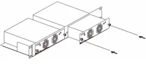 Figure 11 — Install the DPS-500A in the DPS-800
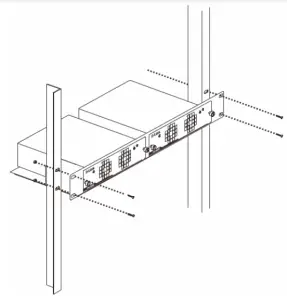 Figure 12 — Install the DPS-800 in an Equipment Rack
Management Options
This Switch can be managed Out-Of-Band (OOB) through the console port on the front panel of the Switch or in-band using any of the copper RJ-45 or SFP ports on the front panel.
Command Line Interface (CLI)This Switch can be managed, out-of-band, by using the console port on the front panel of the Switch. Alternatively, the Switch can also be managed, in-band, by using a Telnet connection to any of the LAN ports on the Switch. The command line interface provides complete access to all switch management features.
SNMP-based ManagementThe Switch can be managed with an SNMP-compatible console program. The Switch supports SNMP v1, SNMPv2c and SNMPv3.
Web User Interface (Web UI)The Web UI can be accessed from any computer running web browsing software from its LAN port when it is connected to any of the copper RJ-45 or SFP ports. This Switch also supports SSL. This management interface is a more graphical representation of the features that can be viewed and configured on this Switch. Most of the features available through the CLI can be accessed through the Web UI. Web browsers like Microsoft’s Internet Explorer, Mozilla Firefox, or Google Chrome can be used.
Connecting to the Console Port
Figure 13 — COM Port Configuration
The front panel of the Switch provides an RJ-45 port that provides an Out-Of-Band (OOB) connection from a computer to the Switch to access the Switch’s Command Line Interface (CLI).
To use the RJ-45 console port, the following equipment is needed:
- A terminal or a computer with both an RS-232 serial port and terminal emulation software
- A console cable with a male DB9 connector on one end and an RJ45 connection on the other
To connect the RJ-45 console port on the Switch to the computer:
- Connect the male DB9 connector on the console cable (shipped with the Switch) to the RS-232 serial port on the computer running terminal emulation software then insert the RJ-45 connector into the RJ-45 console port on the front of the Switch.
To configure the terminal emulation software as follows:
- Select the appropriate serial port (COM1 or COM2).
- Set the data rate to 115200 baud.
- Set the data format to 8 data bits, 1 stop bit, and no parity.
- Set flow control to none.
Connecting to the Switch for the First Time
After successfully connecting to the Switch’s console port and the Switch was turned on, the boot-up procedure will be displayed, as shown below.

After the Switch was successfully booted up, the username prompt will appear, as shown below.

By default, there is no login user account configured on this Switch. Simply press the Enter key twice and the CLI input cursor will be available, as shown below.
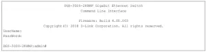
NOTE: By default, there are no login user accounts configured on thisSwitch. For security reasons, it is highly recommended to create a login user account for this Switch.
Logging into the Web UI
Supported Web browsers:
- Microsoft Internet Explorer 7 or above
- Firefox
- Google Chrome
- Safari
To access the Web UI, open a standard web browser, enter the Switch’s IP address into the address bar of the browser, and press the ENTER key. To access the Web UI from normal LAN ports, the default IP address is 10.90.90.90. When connecting to the Web UI of the Switch for the first time, leave the User Name and Password fields blank and click OK since there are no login user accounts created by default on this switch.
 report this ad
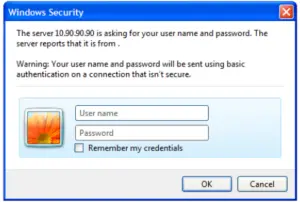
References
[xyz-ips snippet=”download-snippet”]