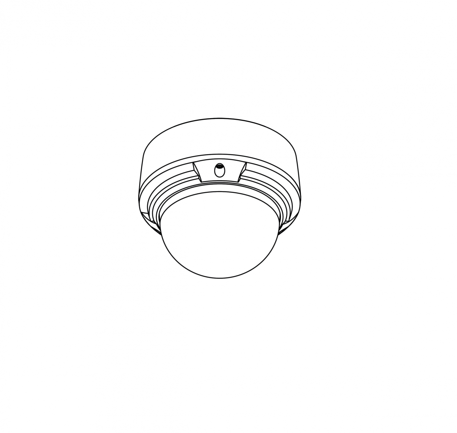
D-Link Vigilance Outdoor Dome Camera

Before You Begin
This installation guide provides instructions for installing and configuring your camera. Additional documentation is also available on the D-Link support website.
Refer to the manual for your model for additional information on how to configure the device using the associated Setup Wizard. The manual and Setup Wizard may be found at https://dlink.com/support/.
Package Contents
This package includes the following items:
- Vigilance Outdoor Dome Camera
- Cable Waterproofing Connector
- Mounting Kit
- Allen Key
- Alignment Sticker
- Documentation
If any of the above items are damaged or missing, please contact your local D-Link reseller.
Note: Using a power supply with a different voltage than the one recommended for the device will cause damage and void the warranty for this product
System Requirements
- Computer running Microsoft Windows®
- Internet Explorer 11
Hardware Overview
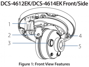
Table 1: Front View Descriptions
|
# |
Feature |
Description |
|
1 |
microSD Slot |
Slot for a microSD card |
|
2 |
Vertical Adjustment Screw |
Loosen to adjust the vertical angle of the camera |
|
3 |
IR LED |
Provides illumination for lowlight environments |
|
4 |
Horizontal Adjustment Screw |
Loosen to adjust the horizontal angle of the camera |
|
5 |
Camera Lens |
Fixed camera lens |
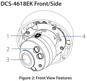
Table 2: Front View Descriptions
| # | Feature | Description |
| 1 | Vertical Adjustment Screw | Loosen to adjust the vertical angle of the camera |
| 2 | IR LED | Provides illumination for lowlight environments |
| 3 | Camera Lens | Motorized camera lens |
| 4 | microSD Slot | Slot for microSD card |
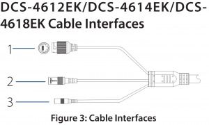
Table 3: Cable Interface Descriptions
| # | Feature | Description |
| 1 | Ethernet Jack | RJ-45 connector for Ethernet. Can also be used to power the camera using Power over Ethernet (PoE) |
| 2 | Power Connector | Connects to an optional 12 V / 1.5 A power adapter (not included) |
| 3 | Reset Button | Press and hold for more than five seconds, then release to perform a factory reset |
Management Options
To configure and manage your camera, it is recommended that you download the associated Setup Wizard and the D-ViewCam software suite, both of which are available from the D-Link website.
Installing the Setup Wizard
- Open a web browser, navigate to www.dlink.com/support/, and select your region.
- On the next screen, enter the model number of your camera in the search bar and click Search. Click the picture of your camera. On the product page, click the Download button next to Setup Wizard.
- Once the executable file has finished downloading, click it and follow the instructions to install the Setup Wizard.
Configuring the Camera
- Ensure that your camera is plugged in (either using a 12 V 1.5 A power adapter or a PoE-enabled device) and connected to your computer with an Ethernet cable.
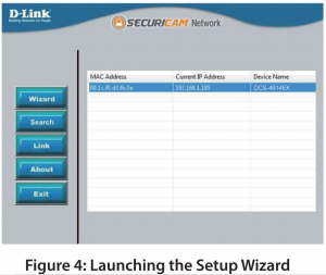
- Open the Setup Wizard. It will display the MAC address and IP address of your camera. If you have a DHCP server on your network, this will be a dynamic IP address. If your network does not use a DHCP server, the network camera’s default static IP 192.168.0.20 will be displayed. Select your camera, then click the Link button to continue.

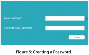
- If this is your first time logging in, you will be prompted to create a password, which must be between 8 and 30 characters and must contain both letters and numbers. Press OK
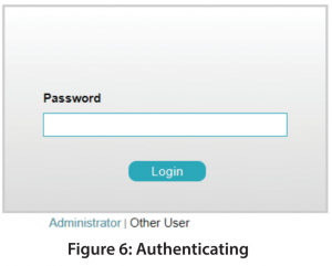
- To view the camera display, on the main screen of the Setup Wizard, click the Search button, then select your camera and click the Link button to open the camera’s web UI. Alternatively, open a web browser and type the camera’s IP address (displayed in step 2) into the URL bar and press Enter. Enter the password you created, and click Login to continue
Installing D-ViewCam
- Open a web browser, navigate to www.dlink.com/support/, and select your region.
- On the next screen, click the D-ViewCam link and click the most recent version to download the D-ViewCam setup wizard (packaged as a zip file).
- Once the file has finished downloading, unzip it, and click the executable file SetupTool.exe. Follow the instructions to install the D-ViewCam software suite.
For advanced viewing options, refer to the D-ViewCam User Manual
Mounting the Camera
Note: It is highly recommended that you configure and test your camera before mounting it.
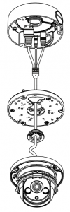
The DCS-4612EK, DCS-4614EK and DCS-4618EK can be installed on the ceiling or wall. The process is identical for both cameras.
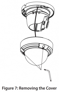
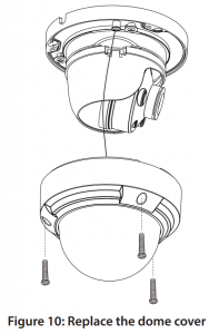
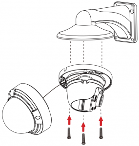
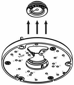
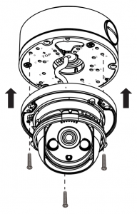
- Use the included T10 or T15 screwdriver to unscrew the three screws on the dome cover and remove it.
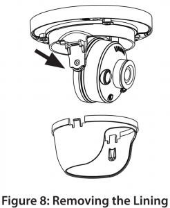
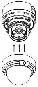
- Press the sides of the plastic lining and gently lift it to remove the lining from the camera.
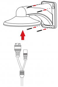
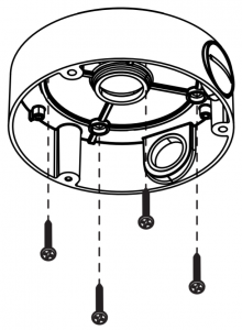
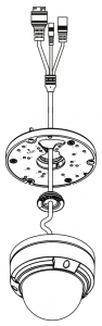
- Place the installation sticker on the ceiling or wall. Using a 4 mm drill bit, drill three holes 30 mm deep into the wall or ceiling. Drive the plastic wall anchors into the holes.
- Insert three mounting screws into the holes in the base of the device. Place the device against the mounting sticker and screw it in to attach it to the wall or ceiling.Three screws with rubber gaskets are provided with DCS-4618EK. To ensure waterproofness you MUST mount the DCS-4618EK with all three of the provided screws.
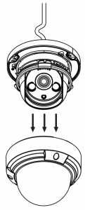
- Reattach the lining to the camera body by sliding it on until it clicks. Replace the dome cover and refasten the screws securing it in place

Adjusting the Lens
The angle, zoom and focus of the lens can adjusted using the web UI. For information on how to do this, refer to the User Manual.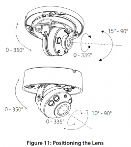
Waterproofing Your Installation
To waterproof your camera, follow the instructions below. A round Ethernet cable, a crimping tool, and RJ-45 plugs are required for this procedure.
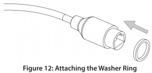
- Place the washer around the base of the Ethernet connector as shown.
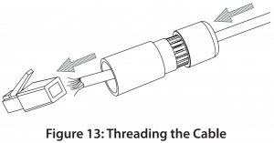
- Thread the bare Ethernet cable through the waterproof connector as shown
- Attach an RJ-45 plug to the end of the cable using a crimping tool.
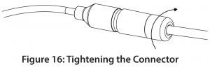
- Connect the RJ-45 plug into the Ethernet connector, then screw the waterproof connector to the Ethernet connector by turning it clockwise about one half-turn.
- Screw the back part of the waterproof connector clockwise until there is a tight seal around the Ethernet cable.
- The power connector and reset button cables are not waterproof. It is recommended to use waterproof tape to protect them. Wind the tape around each cable in an overlapping manner to cover them.


Using the DCS-37-5 Mount (optional)
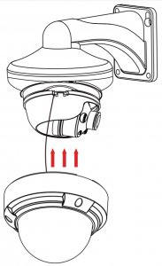
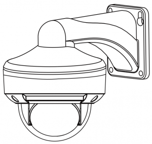
Using the DCS-37-6 Mount (optional)
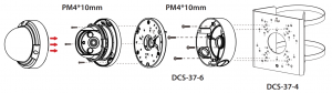
Using the DCS-37-4 Mount (optional)
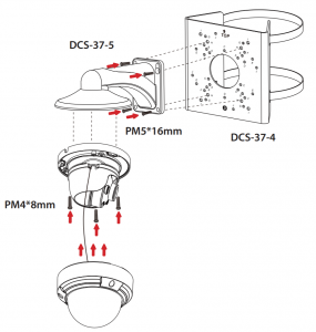
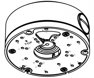
Installation Information
| Model no. |
DCS-37-4 |
DCS-37-5 |
DCS-37-6 |
|||
|
Screw hole |
Screw size | Screw hole | Screw size | Screw hole |
Screw size |
|
| DCS-4612EK DCS-4614EK |
– |
– | B | PM4 * 8mm | B |
PM 4*10mm |
| DCS-4618EK |
– |
– | G | PM4 * 8mm | A |
PM4 * 10mm |
| DCS-37-5 |
H |
PM5*16m m | – | – | – |
– |
| DCS-37-6 |
F |
PM 4*10mm | – | – | – |
– |
Additional Information
If you are encountering problems setting up your network, please refer to the user manual. Product specifications, size and shape are subject to change without notice, and actual product appearance may differ from that depicted on the packaging. Visit your local D-Link website for technical support details. Additional help is available online. To find out more about D-Link products or marketing information, please visit the D-Link support website at http://dlink.com/support/.
Warranty Information
Please visit http://warranty.dlink.com/ for warranty information for your region.

References
[xyz-ips snippet=”download-snippet”]