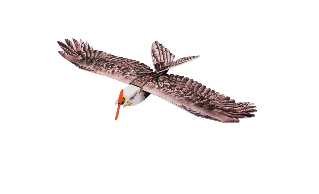
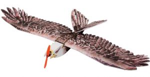
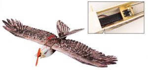
Dancing Wings Hobby Eagle II EPP Airplane Instruction Manual
SAFETY PRECAUTIONS
- This product should not be considered a toy, but rather a complicated and sophisticated flying model. Your safety depends on how you use and fly it, If not correctly operated, could cause injury to you or your family members. Children must be accompanied by an adult at all times if operating this product. Not suitable for children under the age of 14. THIS IS NOT A TOY.
- Do not fly around some restricted location like airports, military bases, residential areas, etc.
- You will need to range check the transmitter to be sure you are not experiencing any interference.
- Always turn on the receiver last after turning on the transmitter and shut off the receiver first before turning off the transmitter.
- If you are only a beginner to the radio control model flying, do not attempt to fly your model without any assistance or advice fromadvanced expert fliers.
- Keep relevant items out of reach of children.
- This product has been flight tested to meet or exceed our rigid performance and reliability standards in normal use,if you plan to perform any high-stress flying, you are solely responsible for taking any and all necessary steps to control movement range and reinforce the body strength.
- This product may include some fiberglass and carbon-fiber reinforced plastic parts,which may cause eye and skin discomfort, pls wear thegoggles or dust-proof clothes when needed.
- Due to air traffic safety control, the products you receive may not have the glue that appears in the list. Please understand and purchase theglue you need at your local stationery store.
KIT
Photos shown here just for reference, the product you received maybe slightlydiffer from the photos due to continuous improvement on products.
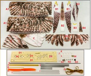
- A1-3:Wing parts
- B1-B4:Fuselage parts
- C:Tail Wing
- D1-D4:Wood pieces
- E:Carbon pieces
- F:Triangle wood
- G:Round Wooden rods
- H:Propeller
- I:Steel wire linkage
- J:Magic tape
- K:servo horns
- L:Plastic clips
- M:EZ-Connector
- N1:Long screws
- N2:Claw nuts
- N3:Short screws
- O:Rubber band
Suggested Equipment
- Suggested Motor: 2212-2216 900-1300kv
- Suggested ESC: 20-30A
- Suggested Servos: 9g*4pcs
- Suggested Propeller: 8-10 inch
- Suggested Battery: 3S 1800-2200mAh
- Radio≥4CH
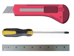
Tools Needed
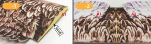
Assemble the Wing
Note: the joints of the parts are bonded with foam glue.
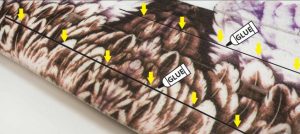
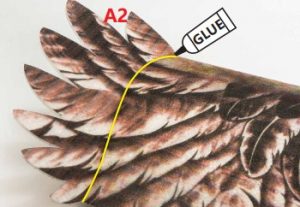
- Apply glue to the wing docking and then bond the two wings together. Thereverse reserved slot lines must be aligned.

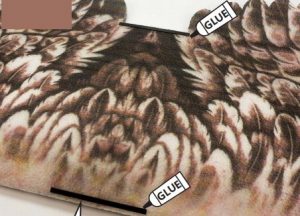
- Reverse the bonded wing to the reverse side, insert the carbon sheets in the reserved groove, and glue it firmly with glue.
- Flip to the front of the wing and attach the carbon sheet to the position above.
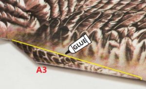
- Apply the wing tips to both ends of the wing, then flip it to the back and use the knife to cut off the spare part of the wing tips.

Assemble the Fuselage
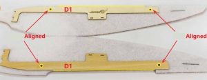
- Attach the wooden piece D1 to the side panel of the fuselage. When pasting, the round holes of the wooden piece are aligned with the round holes of the side panel of the fuselage.
- Paste together the both bonded sides of fuselage through D4,the woodpieces are bonded with quick-drying glue.
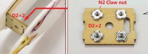
- Attach the motor firewall to the head of the fuselage, pay attention to thenut side facing the inner of the fuselage. The two pieces of the firewall are glued together and the claw nut is installed.
- Paste the B2 at the bottom of the fuselage.
- Paste B3, B4 at the top of the fuselage.


Assemble tail wing
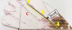
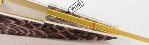
- Insert a carbon sheet in the reserved groove of the tail and glue it with glue.
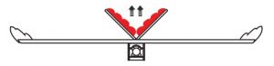
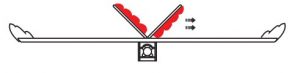
- Paste the triangle wood at the end of the fuselage (as shown above).
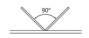
- Paste the two tails onto the triangle wood to make the tail a V-shaped. Pay attention to the positive and negative painting.

Servo, Servo horn and Linkages
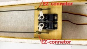
- Install the servo in the middle of the fuselage,install the EZ-connetors onto the rudder arm,and the steel wire rod is inserted into the EZ connector and locked.
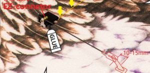
- Install the servo in the reserved hole of the wing, glue it with glue, and bury the servo lines into the reserved slot and guide it to the middle of the fuselage.One end of the steel wire rod is fixed with the EZ connector of the servo arm, the other end is equipped with plastic clip, the servo horn is installed at a suitable position of the aileron, and the plastic clip is connected with the servo horn.
- The linkage rod connecting the servos inside the fuselage passes through the reserved hole at the tail, and the plastic clip is installed at the end. Install the servo horn at the appropriate position on the V-tail rudder surface, and connect the servo horn to the plastic clip.
 One end of the steel wire rod is fixed with the EZ connector of the servo arm, the other end is equipped with plastic clip, the servo horn is installed at a suitable position of the aileron, and the plastic clip is connected with the servo horn.
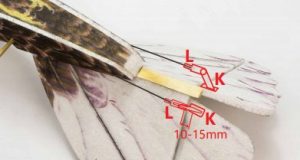
Usually, the control throws set as below:

| (Normal Flying) | 3D (3D Flying only support some models) | |
| Aileron | ±(15°-30°) | ±40 (or larger) |
| Elevator | ±15° | ±40° (or larger) |
| Rudder | ±15° | ±40° (or larger) |
| Flap | ( take-off)15°-20° | Landing)20°-40° |
Some special models will have V-tails, flaps, leading edge wings, etc., which can be used as a reference for conventional flight angles.If you do not confirm and there is no experienced person to guide you, we recommend that you first test at a small angle to confirm that your settings are correct.
Install the Motor and Propeller
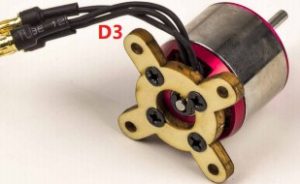
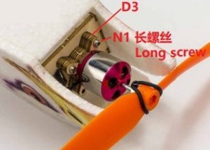
- Secure the motor onto the motor mount D3.
- Secure the motor to the firewall. At this time, according to the size of themotor you selected, pad D3 and adjust to the appropriate length.
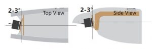
- When installing the motor, you can put some waste wood pieces on the back of the motor seat to adjust the right pull angle and the pull-down angle. Check the specific angle reference on the left.
Assemble the Wing
- Insert the round wood rod into the reserved hole of the fuselage as shown above.
- Place the wing in the center of the fuselage and lock the wing with rubber band as shown above.


Install the electronic equipment Adjust the center of gravity
- Put the battery inside the fuselage, adjust the position of the center of gravity, and then paste it into the fuselage with magic tape.
Control Directions Tests
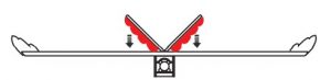
| Elevator | Lifting rod down |
|
| Lifting rod up |
|
|
| Aileron | Steering rod to the right |
|
| Steering rod to the left |
|
|
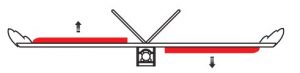
| Rudder | Direction rod to the right |
|
| Direction rod to the left |
|


Remarks: This aircraft can also lock the ailerons, only rely on the V-tail flight.Please refer to the delta wing setting method for the specific setting.

- Cut a small opening in the aileron, insert a carbon sheet, and glue it to seal the aileron.
PRE-FLIGHT CHECKS
- Check/adjust servo centering, in order to adjust the control surface better.
- Double-check the spinning direction of motor at first usage, and sure it’s suitable for your model.
- Set the center of gravity (CG) at the position that manual already marked out. If necessary, add weight to the nose or tail to ensure the best flight performance.
- Double-check the inside of the fuselage, make sure all the equipments are correctly connected; Check the heat-shrink covering material’s surface, Make certain all screws, bolts, cabin and canopy remain secure.
- Take great care when connecting/disconnecting the battery, pls replace the battery immediately once found low voltage or damage to battery.
- The way the internal devices of the fuselage are connected will be related to your transmitter-receiver device. For those transmitter-receiver devices with more functions, you can simplify the connection of the internal devices of the fuselage. Check your device for details to see if it meets the features you need.
- When the power system and transmitter-receiver device are paired for the first time, you may need to set the maximum stroke of the throttle. Please set it yourself.
Dancing Wings Hobby Eagle II EPP Airplane Instruction Manual – Dancing Wings Hobby Eagle II EPP Airplane Instruction Manual –
[xyz-ips snippet=”download-snippet”]