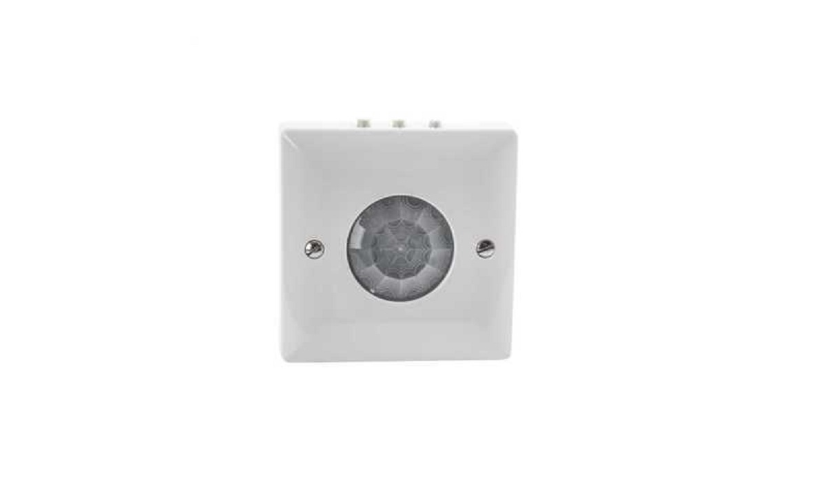

CESF PIR
Ceiling Surface MountedPIR Occupancy Switch (Presence detection)
Input: 220-240 Vac 50Hz
PLEASE READ THESE INSTRUCTIONS BEFORE INSTALLING THE PRODUCT
DANLERS ceiling surface passive infra-red occupancy switches (CESF PIR) can be ceiling mounted on a square pattress box (DANLERS code: PABO).
The CESF PIR incorporates a passive infra-red quad sensor to detect movement of a warm body within its detection zone (diagram A) and a photocell to monitor the ambient light level.
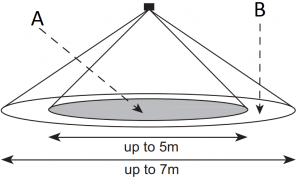
DIAGRAM A (DETECTION)
For optimum coverage recommended mounting height: 2.4 to 5m
A Strong detection zone i.e. person moving arm or walking towards PIRB Secondary detection zone i.e. person walking perpendicular to PIR
Upon detecting movement, if the ambient light is dark enough, the CESF PIR will switch the load on. The ambient threshold can be set by the user to between approximately 30 lux and 1000 lux and maximum (photocell inactive) at the PIR via the LUX adjuster (diagram B).
If no more movement is detected within a pre-selected time, then the CESF PIR will switch the load off. This time lag can be set via the TIME adjuster to 10 seconds, 20 seconds, 40 seconds, 80 seconds, 2 minutes 30 seconds, 5 minutes, 10 minutes, 20 minutes or 40 minutes (diagram B).
CESF PIR also incorporates a sensitivity adjuster, labelled ‘SENS’, to reduce the range and sensitivity of detection (diagram B).
INSTALLATION PROCEDURE
- Please read these notes carefully before commencing work.In case of doubt please consult a qualified electrician.
- POSITIONING: The CESF PIR should be installed to achieve correct coverage of the area, see diagram A. If the photocell override facility is required, the switch must be located above an area where daylight can give greater illumination than the artificial light. Avoid locating this product where it is exposed to windy or drafty conditions (exposed lobbies, open ceiling voids or near ventilation fans) or near heat sources. To cover large areas CESF PIRs should be spaced in a 5 metre grid formation.
- The greatest energy savings will be made if each CESF PIR controls an independent set of lamps. They can be wired in parallel but this should ideally be limited to three, see diagram D.
- Make sure the power is isolated from the circuit. The CESF PIR should be connected as shown in diagrams C & D:L – Live in.N – Neutral in.SL – Switched Line out.
LOADING
See overleaf for loading details.
START-UP MODE
When the PIR is powered up, the PIR will switch on the lighting load for 1 minute then switch it off. After 2 seconds it will switch on again if it detects movement. With TIME set to minimum the load will stay on for 10 seconds so the detection range can be easily assessed. If a manual override-off switch is positioned before the PIR in the circuit (diagrams C & D, note 1) it will do this each time the wall switch is switched on. Alternatively, if the wall switch is placed after the PIR (diagrams C & D, note 2) it will not enter the start-up mode each time.
TIME, LUX AND SENSITIVITY SET UP
For convenience, ensure that the TIME is set to the minimum when setting up the LUX level. Afterwards set the TIME to a value suitable for the application, making reference to diagram B.
The LUX is best set up when the local ambient light is at approximately the minimum desired working light level, a lux meter placed on the surface under the CESF PIR may help. With the LUX set fully clockwise wait for the CESF PIR to switch off. Rotate the LUX adjuster slowly anticlockwise (- to +), whilst waving your hand approximately 1m below the PIR, until the load switches on.
Turn the SENS adjuster fully clockwise for maximum range and sensitivity of the person detector. Turn anti-clockwise for reduced range and sensitivity.
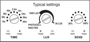
DIAGRAM B (ADJUSTING TIME, LUX & SENSITIVITY)
TROUBLESHOOTING
The load will not switch on:
- The LUX adjuster is set too low and is inhibiting the switch.
- The SENS adjuster is set too low.
- The moving body is not emitting more IR than the background. (Person wearing insulating clothing in a warm environment)
- Person is too far from the PIR switch, see detection diagram.
- Person is moving unusually slowly (perhaps when testing).
The load switches on when nobody is present:
- Heater causing infra-red variations in a small cold room. Reduce the sensitivity adjuster or re-site the CESF PIR.
- Please contact DANLERS for further technical support.
VARIANTS – MAINS VOLTAGE
CESFAPIR Surface mounted PIR absence switch (square enclosure)
CESFPIRAR Surface mounted PIR switch with additional range – 8m maximum (square enclosure)
CESRPIR Surface mounted PIR switch (round enclosure)
CESRAPIR Surface mounted PIR absence switch (round enclosure)
WIRING DIAGRAMS
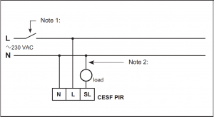
DIAGRAM C (WIRING A SINGLE PIR)
Note 1: Optional manual wall switch for overriding off.Note 2: Alternative position for optional wall switch
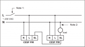
DIAGRAM D (WIRING IN PIRS IN PARALLEL)
Note 1: Optional manual wall switch for overriding off.Note 2: Alternative position for optional wall switch
TECHNICAL DETAILS
| INPUT: | |
| Voltage: | 220 – 240Vac |
| Frequency: | 50Hz |
| LOADING: | |
| Resistive loads: | 6 amps (1500W) |
| Fluorescent: | 6 amps (1500W) |
| LED Drivers and LED lamps and fittings: | 6 amps (1500W) |
| Electronic and wire wound transformers: | 3 amps (750W) |
| CFL and 2D lamps: | 2 amps (500W) |
| Fans: | 1 amp (250W) |
| Minimum load | 2W resistive, suitable for most energy saving lamps, LEDs and emergency fittings. |
| OPERATING CONDITIONS: | |
| The temperature difference between the detection target and the background must be at least 4 °C. | |
| Ambient temperature: | -20… +40 °C (lout 0.05 A) |
| Max. case temperature: | +70 °C |
| Storage temperature: | -25… +75 °C |
| Max. relative humidity: | 0… 80%, non cond. |
| CONNECTORS: | |
| Terminal block Wire size: | 0.5mm2 – 2.5mm2 solid or stranded |
| Wire strip length: | 6-7mm |
| Tightening torque: | 0,4 Nm/4 Kgf.cm |
| MECHANICAL DATA: | |
| Dimensions: | 86mm x 86mm x 22mm |
| Weight: | 98g (unpacked) |
| Degree of protection: | IP20 |
| Protection class: | Built-in Class 2 |
| Material (casing) | Flame-retardant polycarbonate |
| Finish / Colour | Matt /White (RAL 9003) |
| Protection class: | Built-in Class 2 |
| CONFORMITY AND STANDARDS: | |
| EMC emission: | EN60669-2-1:2004 inc. A12:2010 |
| EMC immunity: | EN60669-2-1:2004 inc. A12:2010 |
| Safety: | EN60669-2-1:2004 inc. A12:2010 |
| Environment: | Complies with WEEE and RoHS directives |
| VARIANTS – LOW VOLTAGE: | |
| DANLERS also design and manufacture an extensive range of Ceiling Surface Mounted PIR Occupancy Switch variants some of which are listed below: | |
| CESF PIR 12VACCESF PIR 12VDCCESF PIR 24VACCESF PIR 24VDC | 12V or 24V (ac or dc) operation |
| CESF PIR 12VACVFCESF PIR 12VDCVFCESF PIR 24VACVFCESF PIR 24VDCVF | 12V or 24V (ac or dc) operation Volt Free contacts |
PRECAUTIONS AND WARRANTY
This product conforms to BS EN 60669-2-1 and BS EN 55015.
Please ensure the most recent edition of the appropriate local wiring regulations are observed and suitable protection is provided e.g. a 10 amp circuit breaker and voltage surge protection.
Please ensure that this device is disconnected from the supply if an insulation test is made.
Other DANLERS Product ranges
– Remotely adjusted PIR occupancy switches– Manually adjusted PIR occupancy switches– Daylight linked dimming controls– Photocell switches– Time lag switches– Outdoor security switches– Dimmer switches inc. LED dimming– HVAC controls– Radio remote (RF) controls
Please call for more information or visit our website.
This product is covered by a warranty which extends to 5 years from the date of manufacture.


![]()
DANLERS Limited, Vincients Road, CHIPPENHAM, Wiltshire, SN14 6NQ, UK.Telephone: +44 (0)1249 443377 Fax: +44 (0)1249 443388 E-mail: [email protected]www.danlers.co.uk
Company Registered Number 2570169 VAT Registration Number 543 5491 38
13/04/2021 DAT0098 CESFPIR
References
[xyz-ips snippet=”download-snippet”]