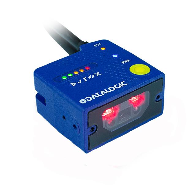
DATALOGIC Matrix 120
Datalogic provides several services as well as technical support through its website. Log on to www.datalogic.com.For quick access, from the home page click on the search icon , and type in the name of the product you’re looking for. This allows you access to download Data Sheets, Manuals, Software & Utilities, and Drawings. Hover over the Support & Service menu for access to Services and Technical Support.
INSTALLATION PROCEDURE
- Using a 2.5 mm hex key, set the Focus Adjustment Screw to one of the three pre-calibrated distances according to your application.
- Physically mount the Matrix 120 reader.
- Make the necessary electrical connections.
- Configure the reader using the X-PRESS interface (AIM, SETUP, LEARN and TEST for simple configuration) or the DL.CODE software configuration program (complete configuration).
HMI X-PRESS™ INTERFACEIn normal operating mode the colors and meaning of the five LEDs are illustrated in the following table:
| READY (green) | indicates the device is ready to operate. |
| GOOD (green) | confirms successful reading. |
| TRIGGER (yellow) | indicates the status of the reading phase. |
| COM (yellow) | indicates active communication on main serial port. |
| STATUS (red) | indicates a NO READ result. |
During the reader startup (reset or restart phase), all the LEDs blink for one second. The single push button gives immediate access to the following relevant functions:
|
|
Test Mode with bar graph visualization to check static reading performance. |
|
|
Focus (Aim) turns on the laser LED to aim the reader at the target. The target should be placed 8 mm to the left and centered vertically with respect to the aiming pattern (cross). |
| Setup to self-optimize and auto-configure photometry parameters. | |
|
|
Learn to self-detect and auto-configure for reading an unknown barcode (by type and length). Only one symbology type can be saved using this method. Performing Autolearn on a second symbology will overwrite the first one. |
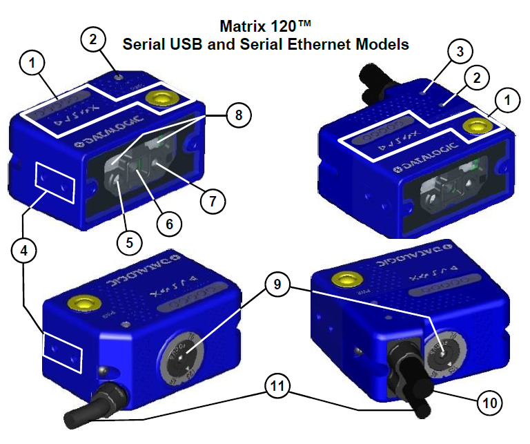
- HMI X-PRESS™ Interface PRESS
- Power On LED
- Ethernet Connection LED
- Mounting Holes (4)
- Aiming System Laser Source
- Lens
- Good Read LED Green
- Internal Illuminators
- Focus Adjustment Screw
- Ethernet Cable
- Power-serial- I/O Cable
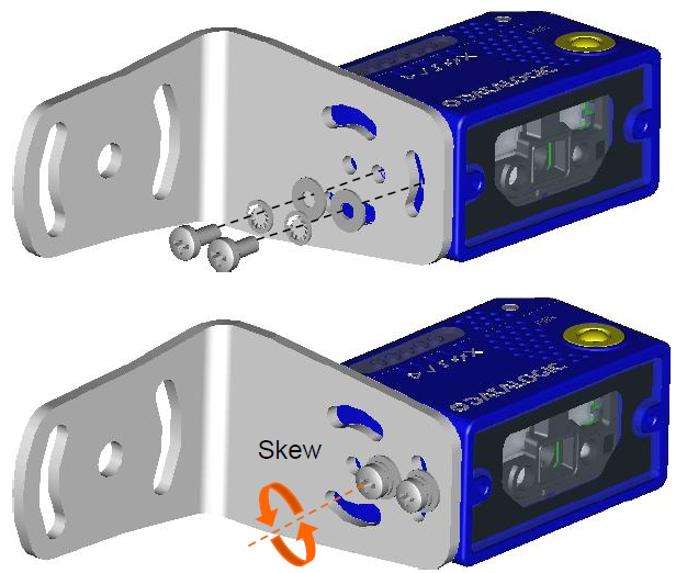
Mounting
- To mount the Matrix 120, use the mounting bracket to obtain themost suitable position for the reader. Common mounting configurations are shown in the figures below.

Electrical Connections

I/O Connections
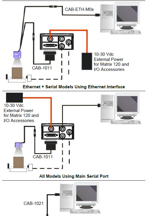
I/O Using CAB-1011 to CBX:
CAUTION: When Matrix 120 is connected to the CBX connection box through CAB-1011, Inputs and Outputs become opto-isolated and maintain the polarity significance of the CBX signals. To function correctly, they all require setting the respective Line Type configuration parameters to NPN. The hardware connection to the CBX can be either NPN or PNPThe electrical features of both inputs at the CBX are:VAB = 30 Vdc max.IIN = 12 mA (CAB-1011) + 12 mA (CBX) max.The following connections refer to Datalogic sensors.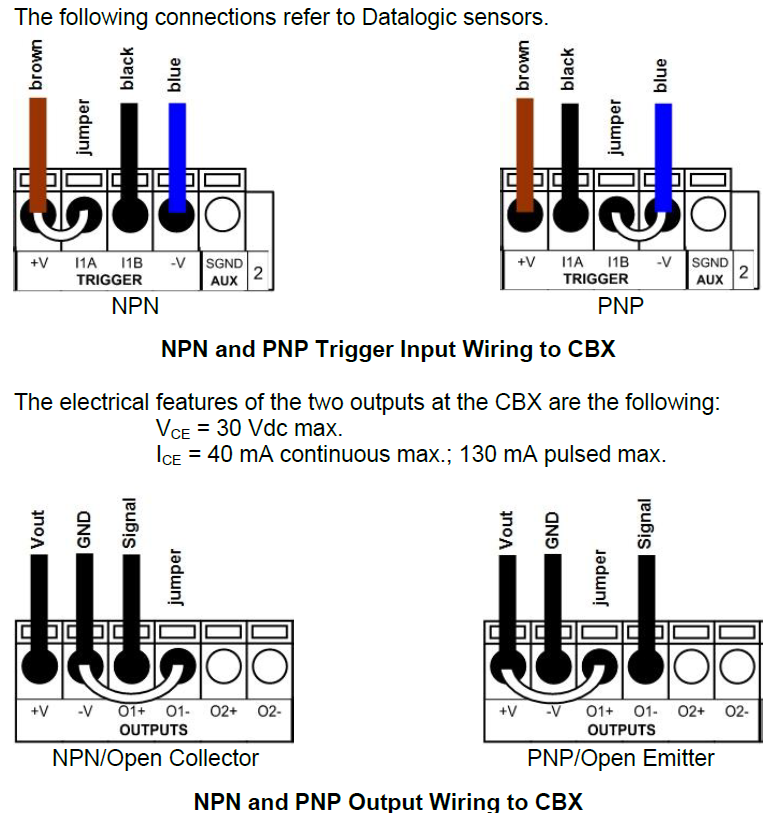
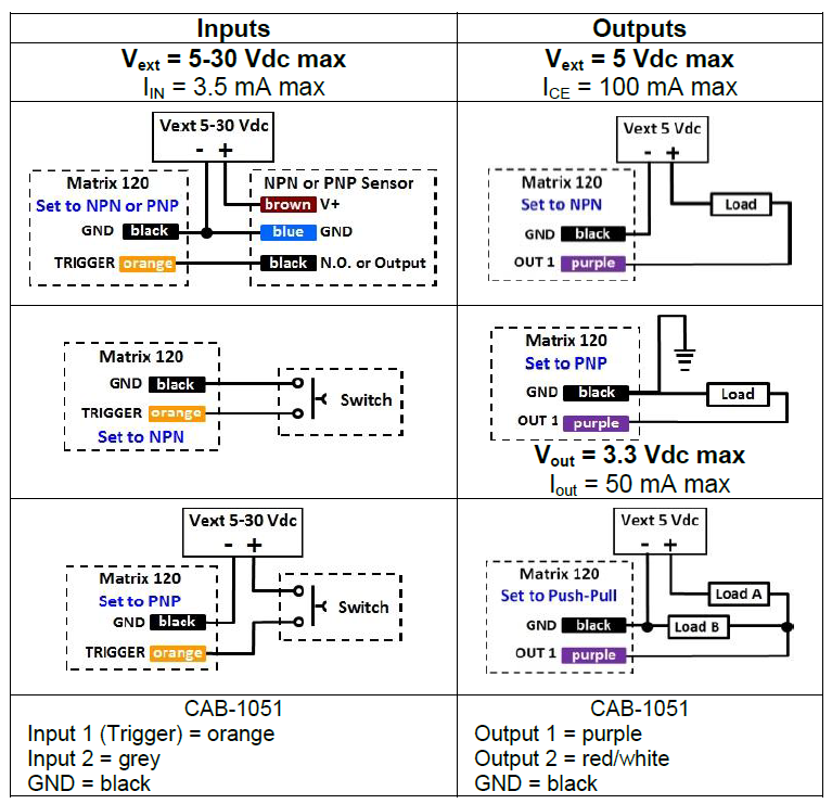
I/O Using CAB-1051:CAUTION: If output devices are powered externally (separate from Matrix 120 power), it is always advised to maintain the same voltage levels used for the Matrix 120 device
Connector Pinouts
| Power – Serial – IO | Ethernet | |
| Pin 1 = TX+ |
4
3 1
2 |
|
| Pin 2 = RX+ | ||
| Pin 3 = TX- | ||
| Pin 4 = RX- | ||
| Use Cat 5e or superior cables. | ||
| 17-pin | Name | Function |
| 9** | O1 | Output 1 (referenced to GND) |
| 8** | O2 | Output 2 (referenced to GND) |
| 6 | IN1 | External Trigger (referenced to GND) |
| 13 | IN2 | Input Signal 2 (referenced to GND) |
| 7 | USB+ | USB Data + (only for USB models) |
| 15 | USB- | USB Data – (only for USB models) |
| 1 | Vdc | Power Supply Input Voltage + |
| 2 | GND | Power Supply Input Voltage – |
| 5 | – | Reserved |
| 3, 4, 14, 16 | NC | not connected |
| Shield | Cable shield connected to chassis and 17-pin connector shell | |
| RS232 Main Serial Interface RS422 FD | ||
| 17 | TX | TX+ |
| 11 | RX | *** RX+ |
| 12 | – | TX- |
| 10 | – | *** RX- |
referenced to GND; Outputs become opto-isolated and polarity sensitive when connected through the CBX connection box. See Reference Manual for connectionmdetails.*** do not leave floating. See Reference Manual for connection details.Focus and PositioningThe Matrix 120 models are factory calibrated at three focus positions (45, 70 and 125 mm for WVGA models; 45, 80 and 125 mm for MP models). Using a 2.5 mm Hex key (Allen wrench), rotate the FocusAdjustment Screw at the back of the reader to one of these three positions for your application.CAUTION: Do not rotate the Focus Adjustment Screw beyond the focus scale limits otherwise damage can occur to the focus mechanism.The following tables show the reading ranges at the three focus positions for Code 128 (1D) and Data Matrix (2D) 10 mil resolution codes:
| WVGA Models (Matrix 120 210-xxx) | |||
| Focus Position | Horizontal FOV | Reading Range (DOF) | |
| 1D | 2D | ||
| 45 | 38 mm
1.5 in |
30 – 80 mm
1.2 – 3.1 in |
25 – 70 mm
1.0 – 2.8 in |
| 70 | 56 mm
2.2 in |
60 – 125 mm
2.4 – 4.9 in |
45 – 100 mm
1.8 – 3.9 in |
| 125 | 95 mm
3.7 in |
95 – 155 mm
3.7 – 6.1 in |
65 – 120 mm
2.6 – 4.7 in |
| MP Models (Matrix 120 310-xxx) | |||
| Focus Position | Horizontal FOV | Reading Range (DOF) | |
| 1D | 2D | ||
| 45 | 40 mm
1.6 in |
30 – 90 mm
1.2 – 3.5 in |
30 – 80 mm
1.2 – 3.1 in |
| 80 | 67 mm
2.6 in |
60 – 130 mm
2.4 – 5.1 in |
60 – 125 mm
2.4 – 4.9 in |
| 125 | 100 mm
3.9 in |
100 – 190 mm
3.9 – 7.5 in |
110 – 165 mm
4.3 – 6.5 in |
| WA Models without Polarizer (Matrix 120 311-xx0) | |||
| Focus Position | Horizontal FOV | Reading Range (DOF) | |
| 1D | 2D | ||
| 45 | 52 mm
2.0 in |
25 – 90 mm
1.0 – 3.5 in |
30 – 65 mm
1.2 – 2.6 in |
| 80 | 86 mm
3.4 in |
65 – 145 mm
2.6 – 5.7 in |
55 – 105 mm
2.2 – 4.1 in |
| 125 | 130 mm
5.1 in |
105 – 180 mm
4.1 – 7.1 in |
80 – 125 mm
3.1 – 4.9 in |
The focus range is continuous to provide fine-tuning for your application
CONFIGURATION
Installing DL.CODE
- On the PC that will be used for configuration, (running Windows 7, 8, or 10), download the DL.CODE mini-DVD .zip file. Extract the files maintaining the folder structure and run the start.hta file to access the installation pop-up. Click on the Install DL.CODE link to run the installation program and follow the installation procedure.
- When the installation is complete the DL.CODE entry is created in the Start>Programs bar under “Datalogic” as well as a desktop icon. Double-click the desktop icon to run it.
- Follow the Matrix 120 Reference Manual to configure:
- Image lighting and code definition (Automatic or Advanced Setup)
- Reading Phase and Communication Channel Selection
- Data Collection Type
- Data Formatting
- Digital Output(s)
TECHNICAL FEATURES
| ELECTRICAL FEATURES | |
| Power | |
| Supply Voltage | 5 to 30 Vdc
(10 to 30 Vdc with CBX) |
| Consumption | 0.4 to 0.1 A Max. |
| Communication Interfaces |
2400 to 115200 bit/s |
| Main
RS232 or RS422 FD |
|
| USB | USB 2.0 Hi-Speed |
| Ethernet1 | 10/100 Mbit/s |
|
Inputs: |
short-circuit protected
(Opto-coupled and polarity insensitive when connected through CBX) |
| Outputs: | short-circuit protected
(Opto-coupled when connected through CBX) |
| OPTICAL FEATURES (see Reference Manual for details) |
| PHYSICAL FEATURES | Serial + USB | Serial + Ethernet |
| Dimensions mm (inch) | 45.4 x 31.1 x 23.5
(1.8 x 1.2 x 1) |
45.4 x 48.5 x 23.5
(1.8 x 1.9 x 1) |
| Weight grams (ounces) | 117 (4.1) with cable | 200 (7.1) with cable |
| Material | Aluminium | Aluminium |
| ENVIRONMENTAL FEATURES | ||
| Operating Temperature2 | 0 to 45 °C (32 to 113 °F) | |
| Storage Temperature | -20 to 70 °C (-4 to 158 °F) | |
| Max. Humidity | 90% non-condensing | |
| Vibration Resistance EN 60068-2-6 | 14 mm @ 2 to 10 Hz; 1.5 mm @ 13 to 55 Hz;
2 g @ 70 to 500 Hz; 2 hours on each axis |
|
| Shock Resistance EN 60068-2-27 | 30g; 11 ms;
3 shocks up and 3 down on each axis |
|
| Bump Resistance EN 60068-2-29 | 30g; 6 ms;
5000 bumps up and 5000 down on each axis |
|
| Protection Class EN 60529 | IP65 | |
| USER INTERFACE | ||
| LED Indicators | Power; Ready, Good, Trigger, Com, Status; Ethernet Network; Green Spot; (see Reference Manual for other LEDs) | |
| Other | X-PRESS™ Keypad Button (configurable via DL.CODE™), Beeper |
1 the embedded Ethernet interface supports application protocols: TCP/IP, EtherNet/IP, PROFINET-IO, Modbus TCP.2 high ambient temperature applications should use metal mounting bracket for heat dissipation.
| SOFTWARE FEATURES | |||
| Readable Code Symbologies | |||
| 1D and stacked | 2D | POSTAL | Digimarc Barcode |
| ·PDF417 · Codabar Standard and ·Code 93 Micro PDF417Pharmacode· Code 128 · EAN-8/13 -(GS1-128) UPC-A/E · Code 39 (including
(Standard and Addon 2 and Full ASCII) Addon 5) Code 32 · GS1 DataBar · MSI Family ·Standard 2 of 5 · Composite ·Matrix 2 of 5 Symbologies ·Interleaved 2 of 5 |
· Data Matrix ECC 200 (Standard, GS1 and Direct Marking)
· QR Code (Standard and Direct Marking) · Micro QR Code · MAXICODE · Aztec Code |
· Australia Post
· Royal Mail 4 State Customer · Kix Code · Japan Post · PLANET · POSTNET · POSTNET (+BB) · Intelligent Mail · Swedish Post |
DWCODE™ * |
| Operating Mode | CONTINUOUS, ONE SHOT, PHASE MODE | ||
| Configuration Methods | X-PRESS™ Human Machine Interface Windows-based SW (DL.CODE™) via Ethernet or Serial Interface
Host Mode Programming sequences sent over Serial or Ethernet TCP interfaces |
||
| Parameter Storage | Permanent memory (Flash) | ||
PATENTS
See www.patents.datalogic.com for patent list.This product is covered by one or more of the following patents:Matrix 120™Design patents: EP003042845; EP003074079Utility patents: EP0996284B1; EP0999514B1; EP1014292B1; EP1128315B1; EP1172756B1; EP1396811B1; EP1413971B1; EP1804089B1; EP2315156B1; EP2517148B1; EP2649555B1; JP4435343B2; JP4571258B2; JP5192390B2; US6512218; US6616039; US6808114, US6877664; US6997385; US7053954; US7387246; US8058600; US8113430; US8368000; US8888003; US8915443; US9268982; US9430689; ZL200680050007.8.
COMPLIANCE
Only connect Ethernet and dataport connections to a network which has routing only within the plant or building and no routing outside the plant or building.
EMC COMPLIANCEIn order to meet the EMC requirements:
- connect reader chassis to the plant earth ground by means of a flat copper braid shorter than 100 mm;
- connect pin “Earth” of the CBX connection box to a good Earth Ground;
POWER SUPPLYThis product is intended to be installed by Qualified Personnel only. This product is intended to be connected to a UL Listed Computer (LPS or “Class 2”) which supplies power directly to the reader or a UL Listed Direct Plug-in Power Unit marked LPS or “Class 2”.EAC COMPLIANCECustoms Union:The CU Conformity certification has been achieved; this allows theProduct to bear the Eurasian mark of conformity.LED SAFETYLED emission according to EN 62471
LASER SAFETY
All Matrix 120s contain one aiming Laser source used to position the reader.These products conform to the applicable requirements of IEC 60825-1 and comply with 21 CFR 1040.10 except for deviations pursuant to Laser Notice N° 50, date June 24, 2007. This product is classified as a Class 1M laser product according to IEC 60825-1 regulations.WARNING: Use of controls or adjustments or performance of procedures other than those specified herein may result in exposure to hazardous visible laser light.LASER RADIATION DO NOT VIEW DIRECTLY WITH OPTICAL INSTRUMENTS CLASS 1M LASER PRODUCT Disconnect the power supply when opening the device duringmaintenance or installation to avoid exposure to hazardous laser light. The laser beam can be switched on or off through a software command.
CE COMPLIANCECE marking states the compliance of the product with essential requirements listed in the applicable European directive. Since the directives and applicable standards are subject to continuous updates, and since Datalogic promptly adopts these updates, therefore the EU declaration of conformity is a living document. The EU declaration of conformity is available for competent authorities and customers through Datalogic commercial reference contacts. Since April 20th, 2016 the main European directives applicable to Datalogic products require inclusion of an adequate analysis and assessment of the risk(s). This evaluation was carried out in relation to the applicable points of the standards listed in the Declaration of Conformity. Datalogic products are mainly designed for integration purposes into more complex systems. For this reason, it is under the responsibility of the system integrator to do a new risk assessment regarding the final installation.
WarningThis is a Class A product. In a domestic environment this product may cause radio interference in which case the user may be required to take adequate measures.
FCC COMPLIANCEModifications or changes to this equipment without the expressed written approval of Datalogic could void the authority to use the equipment. This device complies with PART 15 of the FCC Rules. Operation is subject to the following two conditions: (1) This device may not cause harmful interference, and (2) this device must accept any interference received, including interference which may cause undesired operation.
This equipment has been tested and found to comply with the limits for a Class A digital device, pursuant to part 15 of the FCC Rules. These limits are designed to provide reasonable protection against harmful interference when the equipment is operated in a commercial environment. This equipment generates, uses, and can radiate radio frequency energy and, if not installed and used in accordance with the instruction manual, may cause harmful interference to radio communications. Operation of this equipment in aresidential area is likely to cause harmful interference in which case the user will be required to correct the interference at his own expense.
LEGAL NOTICES© 2016 – 2019 Datalogic S.p.A. and/or its affiliates ALL RIGHTS RESERVED. Without limiting the rights under copyright, no part of this documentation may be reproduced, stored in or introduced into a retrieval system, or transmitted in any form or by any means, or for any purpose, without the express written permission of Datalogic S.p.A. and/or its affiliates.Datalogic and the Datalogic logo are registered trademarks of Datalogic S.p.A. in many countries, including the U.S. and the E.U. Matrix 120, DL.CODE and X-PRESS are trademarks of Datalogic S.p.A. and/or its affiliates. Digimarc® and DWCODE™ are trademarks of Digimarc Corporation. All other trademarks and brands are property of their respective owners.Datalogic shall not be liable for technical or editorial errors or omissions contained herein, nor for incidental or consequential damages resulting from the use of this material.![]()
References
[xyz-ips snippet=”download-snippet”]