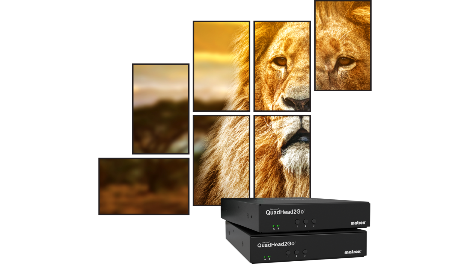
DATAPATH X-series Multi-display Controller
x-Series Quick Start Guide
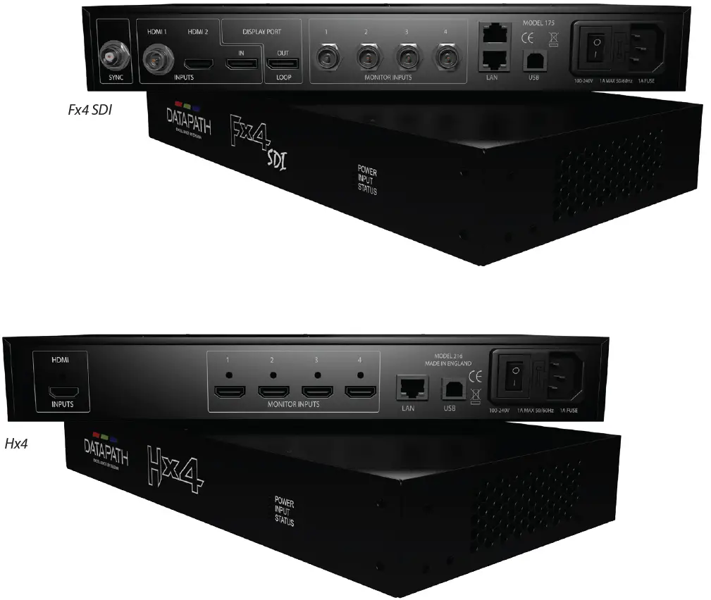
STEP 1 CONNECT INPUTS
Connect your input source to the input connector on the rear of the controller. The input connectors are clearly marked on the rear panel of your controller.
|
Multi-display Controller |
HDMI Inputs |
SDI Inputs |
Display Port Inputs |
| Fx4-HDR |
3 |
– |
– |
| Fx4 |
2 |
– |
1 |
| Fx4-SDI |
1 |
1 |
1 |
| Hx4 |
1 |
– |
– |
Ensure cables are inserted correctly. It is recommended that locking cable connectors are used where possible.
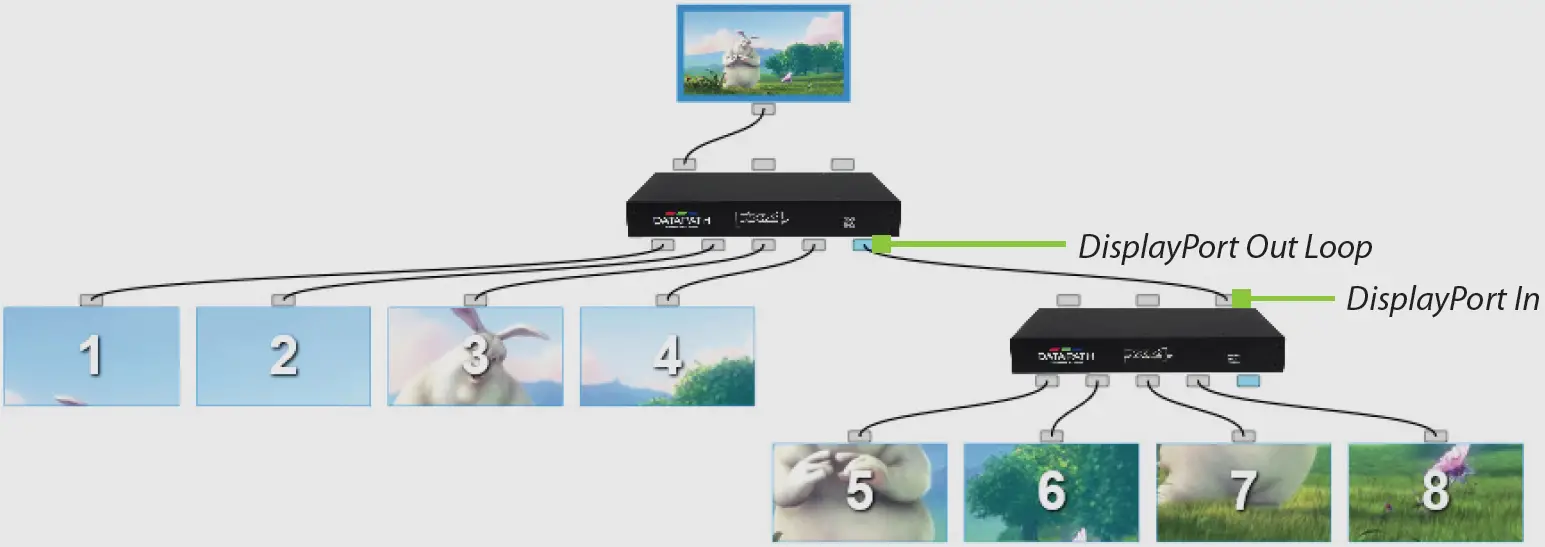
STEP 2 CONNECT OUTPUTS
Connect your display cables to the display output connectors on the rear of your multi-display controllers.The output connectors are clearly marked on the rear panel of your controller. You can connect up to four displays to a single controller.Some models also have a DisplayPort Out Loop. This is used when connecting multiple controllers.Ensure cables are inserted securely it is recommended that locking cable connectors are used where possible.
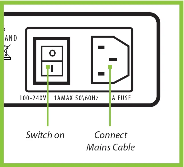
STEP 3 CONNECT MAINS CABLE
When the power is switched on the multi-display controller will boot and the LEDs on the front panel will flash for up to 15 seconds. Should the LED’s continue to flash see the troubleshooting section at the end of this guide.
STEP 4 CONNECTING TO A PC
To successfully configure your multi-display controller, firstly install the Wall Designer application on your PC by downloading the latest version from the Datapath website www.datapath.co.uk.
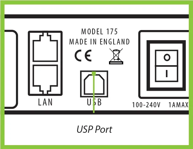
When the controller has booted, connect it to your PC using the USB cable provided. The controller is a plug and play device. Wall Designer will detect it when the layouts are configured.The multi-display controller can also be configured via a Network, (see Step 5).
STEP 5 CONFIGURE VIA A NETWORK
Datapath multi-display controllers have either single or dual Ethernet ports to allow users to add the controller to their network.Controllers with dual Ethernet ports only require one multi-display controller in any chain to be connected to a network. Ethernet loop-through is supported on the second LAN port meaning multiple devices can be connected.

Connect the controller to a network using a LAN connector then open Wall Designer and create your display layout, (see Step 6).
STEP 6 WALL DESIGNER
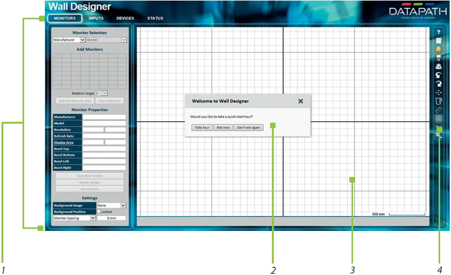
Start | All Programs | Wall Designer |When Wall Designer is opened, the following dialogue is displayed:
|
1 |
Operation Modes: Select outputs, inputs, configure devices and check the status of your multi-display controller. |
|
2 |
Quick Tour Dialogue. |
|
3 |
Virtual Canvas. |
|
4 |
Toolbar. |
It is highly recommended that when using Wall Designer for the first time, all users take the Quick Start Tour.
WALL DESIGNER – SELECTING MONITORSClick on the Monitors tab:
|
5 |
Select your output manufacturer from the drop-down Output Selection list on the left. Then select the model. |
|
6 |
Choose the number of outputs by highlighting cells in the Add Outputs grid. |
|
7 |
Select a Background Image to enhance the Virtual Canvas. |
|
8 |
Click Add Outputs and the selected outputs will populate the Virtual Canvas. Open the Inputs tab. |
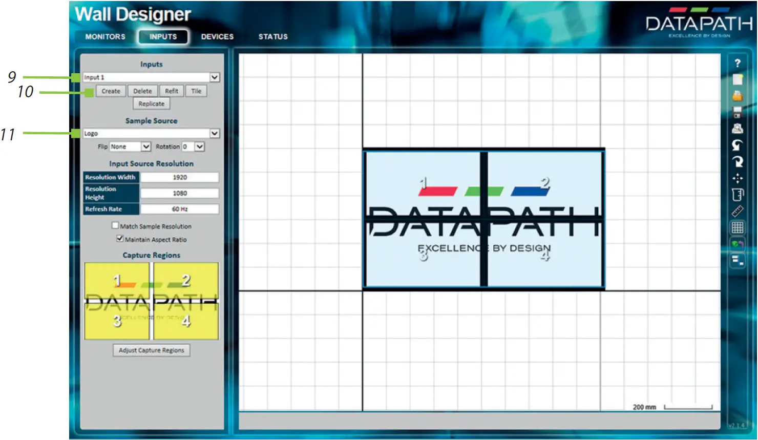
WALL DESIGNER – DEFINING INPUTSClick on the Inputs tabs:
|
9 |
Use the dropdown Inputs list to set up the input sources that are to be displayed on your monitors. |
|
10 |
Click on the Create button. |
|
11 |
Use the drop-down list to select a Sample Source. This will offer a preview of what the display wall will look like on the Virtual Canvas. |
WALL DESIGNER – CONFIGURING HARDWARE DEVICESClick on the Devices tab:
|
12 |
Click on your model of multi-display controller to Auto-configure the device. This will indicate how the displays are connected to the controller. |
|
13 |
Right click of the virtual device and associate it with the physical device connected to your PC or on the network. This will populate the Device Properties.
The Device Properties can be edited. |
|
14 |
Click on Apply Settings to complete the configuration. |
WALL DESIGNER – VIEWING DEVICE STATUSThe Status Panel gives a summary of each associated device.
|
15 |
List of x-Series multi-display devices connected to your computer or LAN. Click on a device to display its status information. |
|
16 |
The status information panel displays a summary of the selected device. This includes details of the Flash and Firmware versions, IP Address, serial number and the average running temperature of the controller. Scroll down to view the status of each output. |
STEP 7 CONNECTING MULTIPLE DEVICES
Where more than four outputs are required, the Auto Configure function in the Devices tab (12) will determine the most logical way to connect all devices.
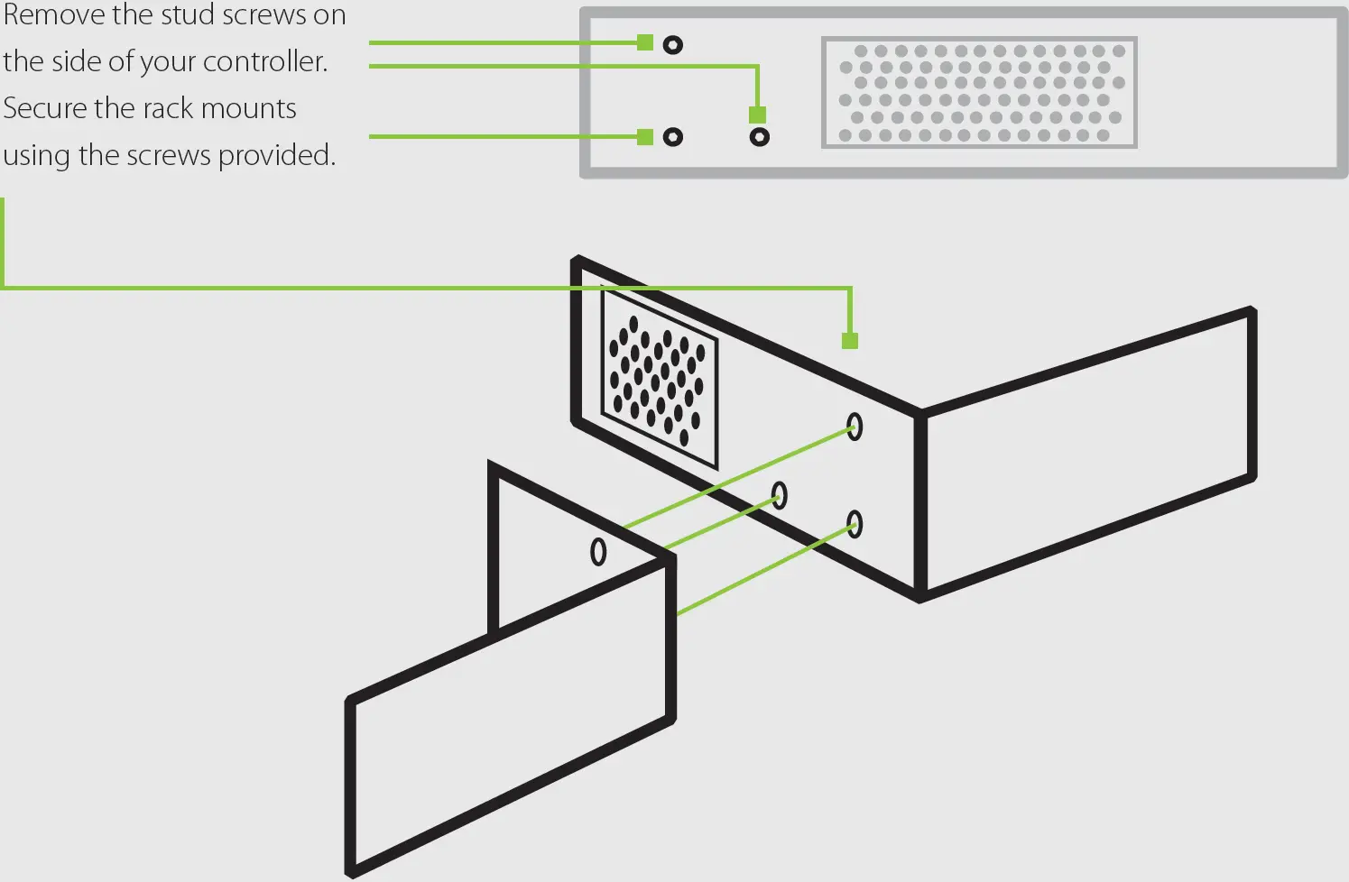
STEP 10 RACK MOUNTING (OPTIONAL)
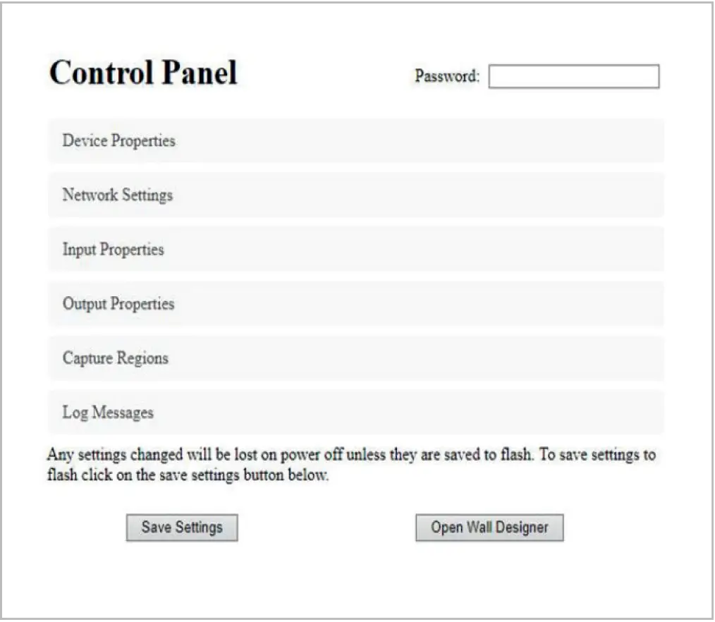
IP CONTROL PANEL
Your multi-display controller has a control panel that can be accessed via an IP connection, simply type in the IP address of the controller into an Internet browser and a control panel is displayed.The control panel allows you to change properties and settings, manually define cropping regions or open the Wall Designer application.
TROUBLESHOOTING
Display Screens Turns Red
If all the display screens turn red, this indicates that there is an issue with HDCP compliance. Check both the input source and the monitors are HDCP compliant.
Front Panel LED Lights Flashing Continuously
On start-up all three lights will flash. After a few seconds the flashing should stop and the power light stays on permanently. If the light continues to flash this indicates that the multi-display controller requires upgrading.
See the User Guide for details on how to upgrade your controller. This can be found on the Datapath website www.datapath.co.uk.
COPYRIGHT STATEMENT
© Datapath Ltd., England, 2019Datapath Limited claims copyright on this documentation. No part of this documentation may be reproduced, released, disclosed, stored in any electronic format, or used in whole or in part for any purpose other than stated herein without the express permission of Datapath Limited.Whilst every effort is made to ensure that the information contained in this Quick Start Guide is correct, Datapath Limited make no representations or warranties with respect to the contents thereof, and do not accept liability for any errors or omissions.Datapath reserves the right to change specification without prior notice and cannot assume responsibility for the use made of the information supplied. All registered trademarks used within this documentation are acknowledged by Datapath Limited.
CERTIFICATION
This device complies with part 15 of the FCC Rules. Operation is subject to the following two conditions: (1) This device may not cause harmful interference, and (2) this device must accept any interference received, including interference that may cause undesired operation.
Datapath Ltd declares that the x-Series Display Controllers comply with the essential requirements and other relevant provisions of Directives 2014/30/EU, 2014/35/EU and 2011/65/EU. A copy of our Declaration of conformity is available on request.
Datapath LimitedBemrose House, Bemrose ParkWayzgoose Drive, Derby, DE21 6XQUK
A full list of product compliance certifications can be found in the product User Guide.
Datapath UK and Corporate HeadquartersBemrose House, Bemrose Park,Wayzgoose Drive, Derby,DE21 6XQ, United KingdomTel: +44 (0) 1332 294 441Email: [email protected]
Datapath North America2490, General Armistead Avenue,Suite 102, Norristown,PA 19403, USATel: +1 484 679 1553Email: [email protected]
Datapath FranceTel: +33 (1)3013 8934Email: [email protected]
Datapath GermanyTel: +49 1529 009 0026Email: [email protected]
Datapath ChinaTel: +86 187 2111 9063Email: [email protected]
Datapath JapanTel: +81 (0)80 3475 7420Email: [email protected]
References
[xyz-ips snippet=”download-snippet”]