![]()
USER MANUALDigital Wireless GatewayU9120-W4(P/N: 44002G-01)
Cautions and Warnings
READ AND SAVE THESE INSTRUCTIONS. Follow the instructions in this installation manual. These instructions must be followed to avoid damage to this product and associated equipment. Product operation and reliability depend on proper usage.
 DO NOT INSTALL ANY DAVID CLARK COMPANY PRODUCT THAT APPEARS DAMAGED. Upon unpacking your David Clark product, inspect the contents for shipping damage. If damage is apparent, immediately file a claim with the carrier and notify your David Clark product supplier.
 ELECTRICAL HAZARD – Disconnect electrical power when making any internal adjustments or repairs. All repairs should be performed by a representative or authorized agent of the David Clark Company.
 STATIC HAZARD – Static electricity can damage components. Therefore, be sure to ground yourself before opening or installing components.
 LI-POLYMER – This product is used with Li-Polymer batteries. Do not incinerate, disassemble, short circuit, or expose the battery to high temperatures. The battery must be disposed of properly in accordance with local regulations.
Overview
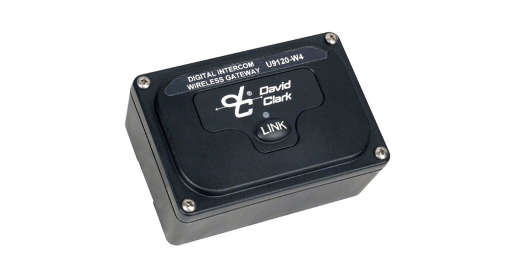
The U9120-W4 (44002G-01) Digital Wireless Gateway is a fixed-mounted wireless communication device that, when used in conjunction with the Digital Intercom System and one or more U9100-series Wireless Belt Stations, becomes part of a digital wireless intercom system. The U9120-W4 provides communication for up to four users and integrates with the Digital Intercom System. Up to four-belt stations can be connected to one gateway.

Installation
Intercom InterfaceThe U9120-W4 is designed to add wireless capability to the Digital Intercom System.MountingSelect a location on a flat surface that is out-of-the-way, and provides adequate room to attach all cables. The U9104-W4 is immersion-proof (IP67). However, where possible the mounting location should be chosen to minimize direct exposure to the elements.
- Position the endpoint on the surface to be mounted and mark the (2) hole locations.
- Drill the (2) holes with a 3/16-inch drill bit.
- Mount the endpoint with #8 mounting screws and nuts/lock-washers (customer supplied).
Alternately, the U9104-W4 may be flush-mounted with the optional flush-mount kit (M9110FM, 44004G-02) or the 44003G-01 gasket-mount kit.
AntennaThe U9120-W4 has an internal antenna. An external antenna may not be necessary but the antenna connector is provided for either the included whip antenna or an optional remote antenna kit (P/N: 40688G-93 for mag- mount, 40688G-96 for permanent install).
Choose an open, clear location for the remote antenna, away from other RF-emitting devices, and route the coaxial cable away from any busy areas, preferably behind panels or in conduits.
This device has been designed to operate with the antennas listed below, and having a maximum gain of 3 dB. Antennas not included in this list or having a gain greater than 3 dB are strictly prohibited from use with this device. The required antenna impedance is 50 ohms.
Acceptable antennas for use with this product:
- Whip Antenna (P/N: 40688G-92)
- Remote Antenna Kit, Mag-Mount (P/N: 40688G-93)
- Remote Antenna Kit, Permanent (P/N: 40688G-96)
Linking
Before a belt station and a gateway can be connected, they must first be linked. As a security measure, the close-link feature requires devices to be in proximity of between 1 to 3 ft (0.3 to0.9m) in order to successfully link. This ensures that the units are not inadvertently linked with other units on the premises.Linking procedure:
- Ensure units are within 1 to 3 ft (0.3 to 0.9m) of each other.
- Simultaneously (within 1-2 sec) press and release the LINK button on the U9120-W4 and the LINK/PTT button on the belt station to link with.
- Amber LEDs will flash on both devices. A momentary red LED indicates a successful close-link.
- Upon successful link, the U9120-W4 will attempt to establish a connection with the belt station.
- Upon successfully establishing the connection the LED on the gateway will flash a green pattern corresponding to the number of belt stations connected.
Tip:Once linked, the devices will not need to be linked again unless they are purged (see Purging).
Each belt station is able to be linked to only one gateway at a time. A gateway can have up to four belt stations linked/connected at one time.
Status Indications
The front panel has a multi-color LED in the center which serves as a status indication for the gateway. Table 1 below lists these states.Table 1: LED Status Indications
| LED Color | Blink Rate | Status |
| Red | Solid | Initializing/power-up |
| Red | Once | Connection Dropped |
| Red | Once | Connection Established |
| Orange | Slow | Idle/Disconnected |
| Orange | Fast | Link/Connection in Progress |
| Orange | Solid | PTT asserted |
| Green | Slow | Connected (pattern indicates the number of belt stations connected) |
Operation
CommunicationCommunication is defined by the Digital Intercom System and configured by the graphical user interface. See the Digital Intercom System manual (19549P-31) for more information.
RangeThe unimpeded line-of-sight range of a belt station and a gateway should be at least 300 ft (100m). If you are in an environment with metal or concrete walls, this range could be reduced. If the belt station enters into a “fringe” reception area, a brief sequence of three beeps will be heard in the headset. This is to serve as a warning of a possible disconnection if conditions are not improved. When possible, the user should attempt to regain line-of-sight contact with the gateway. When the belt station travels out of range of the gateway, a voice prompt will indicate that the connection has been lost. To reconnect, simply move back into range, and connection with the gateway will automatically be re-established, also noted by a voice prompt.
Purging
In some circumstances, it may be desired to “purge” the U9120-W4 of some of its linked belt stations. Typically purging is not necessary unless there are multiple gateways in the same vicinity and you wish to remove a belt station from this gateway and link to a different gateway. A gateway can link up to four belt stations where a belt station can be linked to only one gateway at a time.
Smart PurgeA smart purge is the purge method employed for the U9120-W4, in which only unwanted links are removed from the gateway. When this procedure is complete, only belt stations that are connected to the gateway remain linked. All other belt station links will have been removed (see the belt station User Manual for the individual belt station purging procedure when remaining link purging may be necessary.)
Smart Purge procedure
- Ensure the gateway is powered on and functioning.
- Disconnect all belt stations to be purged (power off the belt stations).
- Verify the number of green LED flashes on the gateway matches the number of belt stations to be kept linked.
- Press and hold LINK button on the gateway for 30 seconds until the LED quickly flashes red.
- Release LINK button.
Troubleshooting
Table 2: Troubleshooting
| Problem | Solution |
| Gateway will not turn on | Check CatSE cable and 131-45 connectors attached between gateway and Master Station |
| Cannot link a belt station | Review Linking procedureEnsure units are within 1. to 3ft (0.3 to 0.9m) of each other while linking Try a Smart Purge and attempt link again |
| Cannot speak over two-way radio | Belt Station PTT not pressed Two-way radio not installed to the system |
Replacement parts
- Whip Antenna (P/N: 40688G-92)
- Remote Antenna Kit, Mag-Mount (P/N: 40688G-93)
- Remote Antenna Kit, Permanent (P/N: 40688G-96)
Care and Maintenance
The U9120-W4 is not user-serviceable. Do not attempt to open the enclosure. If this product requires service, please contact the David Clark Customer Service department:
- Phone: 800.298.6235
- E-Mail: [email protected]
- By Mail: Customer ServiceDavid Clark Company360 Franklin StreetWorcester, MA 01604
When necessary, the U9120-W4 may be wiped down with a mild soap and water mixture.Although it is a sealed device designed to withstand submersion in water to 1 meter, do not unnecessarily submerse this product in water. Avoid storage of this product in direct sunlight or high-temperature environments.
FCC Part 15 Statement
RADIO AND TELEVISION INTERFERENCE
This equipment has been tested and found to comply with the limits for a Class B digital device, pursuant to Part 15 of the FCC rules. These limits are designed to provide reasonable protection against harmful interference in a residential installation. This equipment generates, uses, and can radiate radio frequency energy and, if not installed and used in accordance with the instructions, may cause harmful interference to radio communications. However, there is no guarantee that interference will not occur in a particular installation. If this equipment does cause harmful interference to radio or television reception, which can be determined by turning the equipment off and on, the user is encouraged to try to correct the interference by one or more of the following measures:
– Reorient or relocate the receiving antenna.– Increase the separation between the equipment and the receiver.– Connect the equipment into an outlet on a circuit different from that to which the receiver is connected.– Consult the dealer or an experienced radio/TV technician for help.
You may also find helpful the following booklet, prepared by the FCC: “How to Identify and Resolve Radio- TV Interference Problems.” This booklet is available from the U.S. Government Printing Office, Washington D.C. 20402.
In order to maintain compliance with FCC regulations shielded cables must be used with this equipment. Operation with non-approved equipment or unshielded cables is likely to result in interference to radio & television reception.
Industry Canada Statement
This device complies with Industry Canada license-exempt RSS standard(s). Operation is subject to the following two conditions: (1) this device may not cause interference, and (2) this device must accept any interference, including interference that may cause undesired operation of the device.
Changes or modifications not expressly approved by David Clark Company, Inc. could void the users’ authority to operate the equipment.
FCC Radiation Exposure Statement
This equipment complies with FCC radiation exposure limits set forth for an uncontrolled environment. This equipment should be installed and operated with a minimum distance of 20 centimeters (8 inches) between the radiator (antenna) and your body. This transmitter must not be co-located or operating in conjunction with any other antenna or transmitter.
Usage Restrictions
Due to the UPCS frequencies used, this product is licensed for operation only in the United States of America, Canada, and those countries that have approved the DECT 6.0 Standard.
Specifications
Refer to the U9120-W4 Data Sheet (19549P-49) for specifications.This product is protected by one or more of the following US patents:10,237,415 10,389,884 10,397,408 10,560,825 10,701,211 10,701,212
References
[xyz-ips snippet=”download-snippet”]