![]()
DESCEND™Owner’s ManualDN12 and DN15 Subwoofers
WelcomeThank you for choosing a Definitive Technology Descend subwoofer. In order to ensure that you experience the finest performance possible, we encourage you to take a moment to fully read this owner’s manual and familiarize yourself with the proper installation and setup procedures for your subwoofer. Enjoy!
Safety Precautions

| The lightning flash with the arrowhead symbol, within an equilateral triangle, is intended to alert the user to the presence of uninsulated dangerous voltage within the product’s enclosure that may be of sufficient magnitude to constitute a risk of electric shock to persons. | |
 |
The exclamation point within an equilateral triangle is intended to alert the user to the presence of important operating and maintenance (servicing) instructions in the literature accompanying the appliance. |
- The lightning flash with an arrowhead symbol within an equilateral triangle is intended to alert the user to the presence of non-insulated “dangerous voltage” within the product’s enclosure that may be of sufficient magnitude to constitute a risk of electric shock.• CAUTION: To reduce the risk of electric shock, do not remove cover (or back), as there are no user-serviceable parts inside. Refer servicing to qualified personnel.• The exclamation point within an equilateral triangle is intended to alert the user to the presence of important operating andmaintenance instructions in the literature accompanying the appliance.
 Correct disposal of this product. This marking indicates that this product should not be disposed of with other household wastes throughout the EU. To prevent possible harm to the environment or human health from uncontrolled waste disposal, recycle it responsibly to promote the sustainable reuse of material resources. To return your used device, please use the return and collection systems or contact the retailer where the product was purchased. They can take this product for environmentally safe recycling.
- CAUTION: To reduce the risk of fire or electric shock, do not expose this apparatus to rain or moisture.The apparatus shall not be exposed to dripping or splashing and that objects filled with liquids, such as vases, shall not be placed on the apparatus.
- WARNING: The battery (battery or battery or battery pack) shall not be exposed to excessive heat such as sunshine, fire or the like.
- Read these instructions.
- Keep these instructions.
- Heed all warnings.
- Follow all instructions.
- Do not use this apparatus near water.
- Clean only with a dry cloth.
- Do not block any ventilation openings. Install in accordance with the manufacturer’s instructions.
- Do not install near any heat sources such as radiators, heat registers, stoves, or other apparatus (including amplifiers) that produce heat.Please see additional Safety Precautions on the following page.
Safety Precautions (continued)
- No naked flame sources, such as lighted candles, should be placed on the apparatus.
- Class, I construction should be connected to a mains socket outlet with a protective earthing connection.
- Do not defeat the safety purpose of the polarized or grounding plug. A polarized plug has two blades with one wider than the other.A grounding plug has two blades and a third grounding prong. The wide blade or the third prong is provided for your safety. If the provided plug does not fit into your outlet, consult an electrician for the replacement of the obsolete outlet.
- Protect the power cord from being walked on or pinched particularly at the plugs, convenience receptacles, and at the point where they exit from the apparatus.
- Use only attachments/accessories specified by the manufacturer.
- Use only with the cart, stand, tripod, bracket, or table specified by the manufacturer, or sold with the apparatus. When a cart or rack is used, use caution when moving the cart/apparatus combination to avoid injury from tip-over. The speaker may tip over, causing serious personal injury or death.
- Unplug the apparatus during lightning storms or when unused for long periods of time.
- Refer all servicing to qualified personnel. Servicing is required when the apparatus has been damaged in any way, such as when power supply cord or plug is damaged, when the liquid has been spilled or objects have fallen into the apparatus, when the apparatus has been exposed to rain or moisture, does not operate normally, or has been dropped.
- CAUTION: Danger of explosion if the battery is incorrectly replaced. Replace only with the same or equivalent type.
- The battery (battery or battery or battery pack) shall not be exposed to excessive heat such as sunshine, fire or the like.
- WARNING: Do not recharge non-rechargeable batteries.
- WARNING: The mains plug/appliance coupler is used as the disconnect device. The disconnect device shall remain readily operable.
- CAUTION: To completely disconnect this product from the mains, disconnect the plug from the wall socket outlet. The mains plug is used to completely interrupt the power supply to the unit and must be within easy access by the user.
- The equipment can be used at a maximum ambient temperature of 113 °F (45 °C).
 Correct disposal of this product. This marking indicates that this product should not be disposed of with other household wastes throughout the EU. To prevent possible harm to the environment or human health from uncontrolled waste disposal, recycle it responsibly to promote the sustainable reuse of material resources. To return your used device, please use the return and collection systems or contact the retailer where the product was purchased. They can take this product for environmentally safe recycling.
FCC Information (For US Customers)
- Compliance InformationThis product complies with Part 15 of the FCC Rules. Operation is subject to the following two conditions: (1) this product may not cause harmful interference, and (2) this product must accept any interference received, including interference that may cause undesired operation.
- Important Notice: Do Not Modify This Product.This product, when installed as indicated in the instructions contained in this manual, meets FCC requirements. Modification not expressly approved by Sound United may void your authority, granted by the FCC, to use the product.
- NOTE: This product has been tested and found to comply with the limits for a Class B digital device, pursuant to Part 15 of the FFC Rules. These limits are designed to provide reasonable protection against harmful interference in a residential installation.
This product generates, uses, and can radiate radio frequency energy and, if not installed and used in accordance with the instructions, may cause harmful interference to radio communications. However, there is no guarantee that interference will not occur in a particular installation. If this product does cause harmful interference to radio or television reception, which can be determined by turning the product OFF and ON, the user is encouraged to try to correct the interference by one or more of the following measures:
- Reorient or relocate the receiving antenna.
- Increase the separation between the equipment and receiver.
- Connect the product into an outlet on a circuit different from that to which the receiver is connected.
- Consult the local retailer authorized to distribute this type of product or an experienced radio/TV technician for help.
Notes on Use
- Avoid high temperatures.
- All for sufficient heat dispersion when installed in a rack.
- Handle the power cord carefully.
- Hold the plug when unplugging the cord.
- Keep the unit free from moisture, water, and dust.
- Unplug the power cord when not using the unit for long periods of time.
- Do not obstruct the ventilation holes.
- Do not let foreign objects into the unit.
- Do not let insecticides, benzene, and thinner come in contact with the unit.
- Never disassemble or modify the unit in any way.
- Ventilation should not be impeded by covering the ventilation openings with items such as newspapers, tablecloths or curtains.
- Naked flame sources such as lit candles should not be placed on the unit.
- Observe and follow local regulations regarding battery disposal.
- Do not expose the unit to dripping or splashing fluids.
- Do not place objects filled with liquids, such as vases, on the unit.
- Do not handle the mains cord with wet hands.
- When the switch is in the OFF (STANDBY) position, the equipment is not completed switched off from MAINS.
- The equipment shall be installed near the power supply so that the power supply is easily accessible.
- Do not keep the battery in a place exposed to direct sunlight or in places with extremely high temperatures, such as near a heater.
- Do not bend forcedly the plug on the equipment for the connection between the connector and micro USB/USB cable.
- CAUTION (for amplifier):HOT SURFACE. DO NOT TOUCH.The top surface over the internal heat sink may become hot when operating this product continuously. Do!not touch hot areas, especially around the “Hot surface mark” and the top panel.
 CAUTION (for amplifier):HOT SURFACE. DO NOT TOUCH.The top surface over the internal heat sink may become hot when operating this product continuously. Do!not touch hot areas, especially around the “Hot surface mark” and the top panel.
Cautions on Using Batteries
- WARNING: DO NOT INGEST BATTERY— CHEMICAL BURN HAZARD. The remote control supplied with this product contains a coin/button cell battery. If the coin/button cell battery is swallowed, it can cause severe internal burns in just 2 hours and can lead to death. Keep new and used batteries away from children. If the battery compartment does not close securely, stop using the product and keep it away from children. If you think batteries may have been swallowed or placed inside any part of the body, seek immediate medical attention.
- Insert the specified batteries in the remote control unit.
- Replace the batteries with new ones if the set does not operate even when the remote control unit is operated close to the unit. (The supplied batteries are only for verifying operation. Replace them with the new batteries at an early date.)
- When inserting the batteries, be sure to do so in the proper direction, following the + and – marks in the battery compartment.
- To prevent damage or leakage of battery fluid,– Do not use a new battery together with an old one.– Do not use two different types of batteries.– Do not attempt to charge dry batteries.– Do not short-circuit, disassemble, heat, or dispose of batteries in flames.– Do not keep the batteries in a place exposed to direct sunlight or in places with extremely high temperatures, such as near a heater.
- If the battery fluid should leak, carefully wipe the fluid off the inside of the battery compartment and insert new batteries.
- Remove the batteries from the remote control unit if it will not be in use for long periods.
- Used batteries should be disposed of in accordance with local regulations regarding battery disposal.
- The remote control unit may function improperly if rechargeable batteries are used.
- Explosion risk exists if the battery is replaced by an incorrect type.
For California Customers OnlyThis product contains a battery that contains perchlorate material—special handling may apply.See https://dtsc.ca.gov/perchlorate/
 EU Declaration of ConformityHereby, Sound United, LLC declares that our product is in compliance with the following EU/EC Directives:
- EMC:2014/30/EU
- LVD:2014/35/EU
- RoHS: 2011/65/EU and amendment Directive (EU) 2015/863
- ErP: EC regulation 1275/2008 and its framework directive 2009/125/EC including amendment 801/2013
EU importer/contact:Sound United Europe, a division of D&M Europe B.V.Beemdstraat 11, 5653 MAEindhoven, The Netherlands
 UKCA Declaration of ConformityHereby, Sound United, LLC declares that our product is in compliance with the followingUK regulations:
- Electrical Equipment (Safety) Regulations 2016
- Electromagnetic Compatibility Regulations 2016
- The Restriction of the Use of Certain Hazardous Substances in Electrical and Electronic Equipment Regulations 2012
- Eco-design for Energy-Related Products Regulations 2010
UK Importer: D&M Audiovisual Ltd.Cells 1 & 2 Topshop, 6 Old London RoadKingston Upon Thames KT2 6QF UK
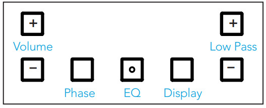
Getting To Know Your Subwoofer
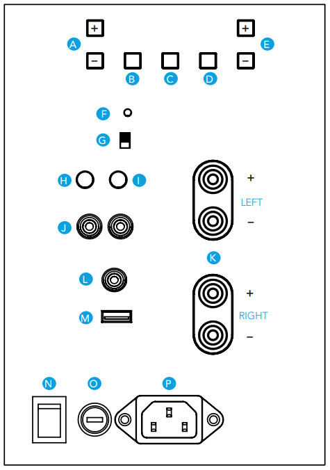
| A | VOLUME UP/DOWN BUTTON |
| B | INTELLIGENT PHASE CONTROL BUTTON |
| C | EQ BUTTON |
| D | DISPLAY BRIGHTNESS BUTTON |
| E | LOW PASS FILTER UP/DOWNBUTTON |
| F | LED POWER INDICATOR |
| G | AUTO/ON/12V 3-WAY SWITCH |
| H | IR IN |
| I | 12V TRIGGER |
| J | LINE IN |
| K | HIGH-LEVEL INPUT (LEFT/RIGHT) |
| L | LFE IN |
| M | SERVICE PORT ONLY |
| N | POWER ON/OFF SWITCH |
| O | FUSE (T6.3AL / 250V) |
| P | AC POWER INLET |
Getting Started
- Plug in the subwoofer to the wall outlet and power up the subwoofer using the power switch on the amplifier panel.
- Set the volume to the V20 setting on the front panel display.
- Set the low-pass control according to the chart on page 18.Pro Tip: Low pass frequency is usually set too high in most systems, especially if the speakers you are using don’t have an additional high pass filter being applied. Chances are you can lower the low pass frequency on your subwoofer.
- If you are using an audio processing unit that has a built-in room correction function, follow the instructions for that process.
- If you are not using a piece of equipment that has built-in room correction, follow step 6 below using multiple media sources (music, movies, TV), and tune the volume of the subwoofer to match the volume of your set of speakers.
- Tune the low-pass setting on your subwoofer according to the amount of “High-Bass” or “LowMidrange” signal being produced by your system. If the media sounds “muddy”, “chesty”, or “boomy”, turn down the low pass frequency until your system sounds even. If the media’s low end sounds “thin”, “detached”, or “uneven”, turn up the low pass frequency until your system sounds even.
Positioning the Subwoofer
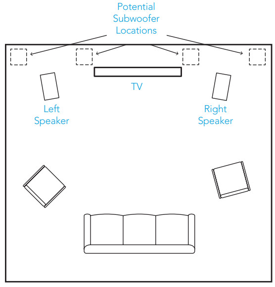
Room Layout for Optimal Listening Experience
There are some general guidelines that you should bear in mind when locating your subwoofer:
- For best results, place the subwoofer on the same side of the room as your front speakers.
- Placement near walls and in a corner will increase the subwoofer’s output, but the sound may be “muddy” or “boomy.”
- An acoustic effect called “standing waves” or “room modes” may cause uneven bass at various locations throughout the room. This phenomenon is a function of the dimensions of the room and not due to the design of the subwoofer. If there is less bass at the main listening position than at other areas of the room, move the subwoofer until you hear full bass at the main listening position.
- Moving the subwoofer even a foot or two can dramatically change the bass output and quality. Experiment with subwoofer placement to achieve the highest performance.
- The subwoofer may be placed inside a cabinet, provided there is a clearance of at least 2 inches (50 mm) around the front, back, sides, and top of the subwoofer. The front of the cabinet should be completely open or covered with an open mesh grille, screen, or cloth.
AC Mains (Power) Connection
The subwoofer has a 3-position power options switch:
- Always on
- Auto on via signal (recommended)
- 12V trigger.
Please note that if you hear a noise from the speaker when the amp powers up or down, this is normal.The blue LED on the back panel will light up when a signal is detected and the amplifier turns on.The LED is red when in standby and no signal is detected. Please note that after the cessation of a signal, it may take up to an hour for the amplifier to actually turn off. This is nothing to be worried about as the amp will be in a low idle mode which uses very little power (less than 1/2 Watt).To prevent accidental damage to your subwoofer from overdriving the system, the subwoofer features an internal overload protection circuit, which will turn the subwoofer off or down when overdriven or overheated and will then resume normal operation after a few minutes.
Connection and Setup
There are three options for connecting input to your subwoofer, LFE INPUT, LINE IN, and SPEAKER LEVEL IN:
1 LFE INPUT SETUP

This method is recommended for home theater systems with receivers or audio processors with built-in bass management. Anything that is attached to a receiver with bass management should have the low-pass filter turned off on the subwoofer by setting it to LFE on the digital display.
- Power off the amplifier/receiver and disconnect the subwoofer from the AC socket.
- Connect a standard RCA cable from the subwoofer/LFE output of your receiver to the LFE input of the subwoofer.
- Connect the subwoofer to an AC power source and turn it on (see page 12).
- Start with the default volume, which is set at V20.
- Increase the Low Pass filter setting on the subwoofer until “LFE” appears on the subwoofer’s display.
- Turn on the receiver’s power and access the “speaker setup” or “speaker configuration” menu.
- Set the subwoofer to “Yes” or “On”.
- Set the main, center, and surround speakers’ lowpass filters to an appropriate frequency (see page 18 for a guide).
- For further setup, follow the instructions of the audio processing unit, or run an automatic bass management setup on the audio processor.
2 LINE IN SETUP

This method is best for systems with no LFE/ subwoofer output jack such as 2-channel systems.
- Power off the amplifier/receiver and disconnect the subwoofer from the AC socket.
- Connect standard RCA cables from the front left and right pre-out jacks of the receiver.
- Connect the subwoofer to an AC power source and turn it on (see page 12).
- Start with the default volume, which is set at V20.
- Set low-pass filter on the subwoofer to the appropriate frequency (see page 18 for guidance).
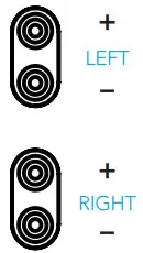
3 SPEAKER LEVEL IN SETUP (best for amps/ receivers with no LFE/subwoofer or pre-out jacks)Note: Speaker Level In is labeled High-Level Input on the back panel of the subwoofer.
- Power off the amplifier/receiver and disconnect the subwoofer from the AC socket.
- Connect standard speaker cables from the speaker output terminals of the amplifier/receiver. Most amplifiers and receiver speaker terminals allow two sets of wires to be connected to one terminal set (one for the main speaker and one for the subwoofer).IMPORTANT NOTE: One terminal on each channel input is marked with a red band (+) and the other is marked with a black band (–). Make certain that you connect the wire from the red (+) terminal of your amplifier or receiver to the red (+) terminal of the subwoofer and the wire from the black (–) terminal of your amplifier or receiver to the black (–) terminal of the subwoofer. It is essential to connect all speakers in the system to the amplifier in the same way (to the correct polarity.) If you experience poor bass, one or more of the channels may be connected to the incorrect polarity and may need to be rewired. Pay close attention and connect positive to positive and negative to negative on all channels.
- Connect the subwoofer to an AC power source and turn it on (see page 12).
- Start with the default volume, which is set at V20.
- Proceed to page 15 for subwoofer adjustment and system tweaking.
 IMPORTANT NOTE: One terminal on each channel input is marked with a red band (+) and the other is marked with a black band (–). Make certain that you connect the wire from the red (+) terminal of your amplifier or receiver to the red (+) terminal of the subwoofer and the wire from the black (–) terminal of your amplifier or receiver to the black (–) terminal of the subwoofer. It is essential to connect all speakers in the system to the amplifier in the same way (to the correct polarity.) If you experience poor bass, one or more of the channels may be connected to the incorrect polarity and may need to be rewired. Pay close attention and connect positive to positive and negative to negative on all channels.
OTHER CONNECTIONS:12 V trigger (optional): In a system utilizing 12V control systems, connect a cable with 3.5! mm tip/ ring male plugs to the 12 V trigger output of the system’s receiver or preamp/processor for one-button system turn-on.
IR Remote (optional):In installations where the subwoofer is in a cabinet or otherwise blocked, the remote will not work. Connect an IR remote repeater eye (optional, available from most audio/video specialty dealers) to the IR remote jack on the subwoofer’s amplifier panel. Position therepeater’s eye within clear view of your main listening position.
Adjusting and Using the Descend Subwoofer
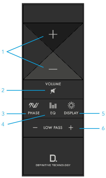
Remote GuideThe remote is the best tool for perfectly adjusting your subwoofer to achieve seamless blending with your main speakers. If you misplace your remote, the most often used controls are duplicated on the rear amp panel.NOTE: If the line of sight from your listening position to the display area of the subwoofer is obstructed, the remote will not work. To remedy the problem, connect an IR remote repeater eye (optional, available from most audio/video specialty dealers) to the IR remote jack on the subwoofer’s amplifier panel.The Volume, Low-Pass Filter, EQ and Phase controls are duplicated on the amplifier panel.
- Volume +/–: Increases/decreases the subwoofer’s loudness. Note: The volume range goes from 0 to 40.
- Mute: Turns off subwoofer sound.
- Phase: Adjusts the relative phase of the output signal. The phase can be adjusted from -135 to 180 degrees in 45-degree increments.
- EQ: There are three program-specific equalization settings: Loud, Deep, and Flat. See Selecting EQ Modes on page 17 for more information.
- Display Brightness: Pressing this button toggles the display brightness. Available settings are Max, Dim1, Dim2, and Off.
- Low-pass filter up/down: The low-pass filter can be adjusted from 40Hz to 150Hz. If the subwoofer is connected via LFE, increase the low-pass filter until “LFE” appears on the front display.
Adjusting for Best Performance
In an ideal audio system, the subwoofer works “invisibly”, simply adding deep, loud bass without calling attention to itself and blending seamlessly with the main speakers so it appears that the main speakers are making all the sound. The key to seamless main speaker/subwoofer blending is finding the perfect crossover frequency, equalization, and phase settings for your system. The best placeto make those “set and forget” adjustments is from your listening chair via the wireless remote. If your receiver has a built-in Audyssey or a similar auto-setup/ room correction function, run that first. In most cases that is all the adjustment, you will need.
NOTE: The auto-setup functions work best when the subwoofer is connected to the LFE/subwoofer output.
- Sit in your favorite listening position with the remote in hand.
- Play a piece of music you are very familiar with that has good deep bass content.
- Adjust the volume up or down to taste. The bass should have an impact without sounding too “heavy.”
- Using the Subwoofer Low-Pass Filter Guide on page 18 as a starting point, adjust the LP up or down until there is a smooth transition between the main speaker and subwoofer. Play a recording with male vocals and string bass. Turn down the LP filter frequency until the vocals sound rich but not “thick” or “chesty.” Turn it up if the vocals sound “thin” or lacking in body.
- Push the Phase button on the remote control to adjust the Intelligent Phase Control setting on the subwoofer. Then listen to how well the subwoofer blends with your speaker system by how little you can tell the difference of sound coming from your speakersand subwoofer. This may also fix some unevenness in the frequency response of your system. If you can’t hear a difference between settings, it is recommended that you leave the setting at 0 degrees.
- If you notice any of the following, you may need to adjust the subwoofer input sensitivity setting:
- ‘LIMIT’ appears regularly on the subwoofer display.
- The subwoofer distorts at peaks in the audio signal.
- The subwoofer volume is at the maximum setting (40) and is still not loud enough.To adjust the input sensitivity setting, see Changing the Input Sensitivity Setting.
Changing the Input Sensitivity SettingPerform the following steps to adjust the input sensitivity setting:
- Press and hold the Phase button on the back panel for 5 seconds to enter Edit mode.
- Release the button when the status indicator blinks blue.
- Press the Low Pass Filter Up/Down button to select an input sensitivity setting (-12 dB, -6 dB or 0 dB will appear on the front display).Note: You will likely not need to change this setting unless you are using the subwoofer with vintage or atypical audio equipment.
- Press and hold the Phase button on the back panel for 5 seconds to save the setting.
- Play content and listen to the sound to verify the subwoofer volume is now to your liking. Readjust the volume and input sensitivity settings as needed.
Selecting EQ Modes
The three equalizations (EQ) modes are variations in frequency response. They allow you to adjust for program material differences. Use the setting(s) that best suit your listening preferences.
- Loud: This is the best setting to use whenachieving maximum volume levels with minimal distortion. Use when the volume is more important than playing the lowest frequencies.
- Deep: This setting maximizes the deepest octave bass response at the sacrifice of maximum volume level. CAUTION: This setting should not be used at high-volume levels.
- Flat: This setting is the recommended starting point. No changes to subwoofer EQ are applied.
Subwoofer Low-Pass Filter Guide
| MAIN FRONT SPEAKER TYPE | SUGGESTED SETTINGS |
| LARGE, FULL-RANGE FLOOR STANDING | 40–100 HZ |
| SMALL FLOOR STANDING AND LARGE BOOKSHELF | 60–100 HZ |
| SMALL BOOKSHELF/MINI-MONITORS/LARGE SATELLITES | 80–120 HZ |
| SMALL SATELLITES | 100–140 HZ |
| USING LFE FROM A RECEIVER OR PRE-AMP WITH INTERNAL BASS MANAGEMENT | LFE |
Specifications
| MODEL | DN12 | DN15 |
| DIMENSIONS | 18.0 X 18.7 X 19.1 IN(458.2 X 475.5 X 484.8 MM) | 22.0 X 22.7 X 23.5 IN(558.5 X 577.6 X 597.9 MM) |
| PRODUCT WEIGHT | 73.1 LBS (33.2 KG) | 114.6 LBS (52.0 KG) |
| DRIVER COMPLEMENT | 12 IN WOOFER WITH2 X 12 IN BASS RADIATOR | 15 IN WOOFER WITH2 X 15 IN BASS RADIATOR |
| FREQUENCY RESPONSE | 17–200 HZ | 12–200 HZ |
Service
Service and warranty work on your Definitive Technology loudspeaker will normally be performed by the Definitive Technology dealer or importer.If, however, you wish to return the speaker to us, please contact us first, describing the problem and requesting proper authorization.
NOTE: Definitive phone and email technical support are only offered in English.Product ServicingPlease note that the address given below is the address of our offices only. Under no circumstances should loudspeakers be shipped to our offices or returned without contacting us first and obtaining return authorization.Technical AssistanceIf you have any questions, please contact the Definitive Technology dealer or importer where you purchased your product. If they are unable to help you, please contact us directly.
1-800-228-7148www.DefinitiveTechnology.comEmail: finitiveTech.comtwitter: @DefinitiveTech
Each subwoofer leaves our plant in perfect condition. Any visible or concealed damage most likely occurred in handling after it left our plant and should be reported at once to your Definitive Technology retailer where you purchased your product. Please unpack your system carefully. Save all cartons and packing material in case you move or need to ship your system.Record the serial number found on the back of the subwoofer.Serial Number: _______________________________
US:5541 Fermi CourtCarlsbad, CA 92008EU :Sound United Europe a division of D&M Europe B.V.Beemdstraat 11, 5653 MA EindhovenThe NetherlandsUK:D&M Audiovisual Ltd.Cells 1 & 2 Kopshop 6 Old London RoadKingston Upon Thames KT2 6QF UK
Limited Warranty
5-Years for Drivers and Cabinets, 3-Years for Electronic ComponentsDefinitive Technology, LLC (herein “Definitive”), warrants to the original retail purchaser only that this Definitive loudspeaker product (the “Product”) will be free from defects in material and workmanship for a period of five (5) years covering the drivers and cabinets and three (3) years for the electronic components from the date of the original purchase from a Definitive Authorized Dealer. If the drivers, cabinets, or electronic components of the Product have a defect in material or workmanship, Definitive or its Authorized Dealer will, at its option, repair or replace the warranted piece for the limited period of time provided in this warranty at no additional charge, except as set forth below. All replaced parts and Product(s) become the property of Definitive.The product that is repaired or replaced under this warranty will be returned to you, within a reasonable time, freight collect. This warranty is non-transferable and is automatically void if the original purchaser sells or otherwise transfers the Product to any other party. This Warranty does not include service or parts to repair damage caused by accident, misuse, abuse, negligence, inadequate packing or shipping procedures, commercial use, the voltage in excess of the rated maximum of the unit, the cosmetic appearance of cabinetry not directly attributable to defects in material or workmanship. This warranty does not cover the elimination of externally generated static or noise, or the correction of antenna problems or weak reception. This warranty does not cover labor costs or damage to the Product caused by installation or removal of the Product. Definitive Technology makes no warranty with respect to its products purchased from dealers or outlets other than Definitive Technology Authorized Dealer. The warranty is automatically void if: 1) The product has been damaged, altered in any way, mishandled during transportation, or tampered with. 2) The product is damaged due to accident, fire, flood, unreasonable use, misuse, abuse, customer applied cleaners, failure to observe manufacturers warnings, neglect or related events. 3) Repair or modification of the Product has not been made or authorized by Definitive Technology. 4) The product has been improperly installed or used. The product must be returned (insured and prepaid), together with the original dated proof of purchase to the Authorized Dealer from whom the Product was purchased, or to the nearest Definitive factory service center. The product must be shipped in the original shipping container or its equivalent. Definitive is not responsible or liable for loss or damage to the Product in transit. This limited warranty is the only express warranty that applies to your product. Definitive neither assumes nor authorizes any person or entity to assume for it any other obligation or liability in connection with your product or this warranty. All other warranties, including but not limited to express, implied, warranty of merchantability or fitness for a particular purpose, are expressly excluded and disclaimed to the maximum extent allowed by law. All implied warranties on products are limited to the duration of this expressed warranty. Definitive has no liability for acts of third parties. Definitive’s liability, whether based on contract, tort, strict liability, or any other theory, shall not exceed the purchase price of the product for which a claim has been made. Under no circumstance will Definitive bear any liability for incidental, consequential or special damages. The consumer agrees and consents that all disputes between the consumer and Definitive shall be resolved in accordance with California laws in San Diego County, California. Definitive reserves the right to modify this warranty statement at any time. Some states do not allow the exclusion or limitation of consequential or incidental damages, or implied warranties, so the above limitations may not apply to you. This warranty gives you specific legal rights, and you may also have other rights which vary from state to state. This product complies with the essential requirements of EMC Directive 89/336/EEC.Copyright © 2021 Definitive TechnologyAll rights reserved.
References
[xyz-ips snippet=”download-snippet”]