DELL AW3821DWB 38 Inch Curved Gaming Monitor User Guide
Disassembly Procedures
- Turn off power
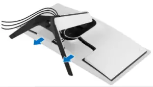
- Place monitor head on U3818DW curve sponge jigCarefully slide and remove the I/O cover from the monitor.

- Disconnect the cables from the monitor and slide them out through the cable management slot on the stand riser.
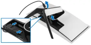
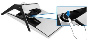
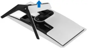
- Press and hold the stand release button
- Lift the stand up and away from the monitor.
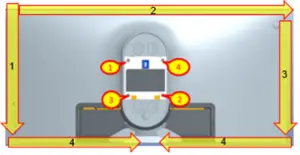
- Unlock 4 screws on rear coverUse hands or scraper bar to disassemble Rear Cover from the monitor.Notice the disassembly order:Left Side=> Top Side=>Right Side=>Bottom Side(Screw Torque: 8-10 kgf)
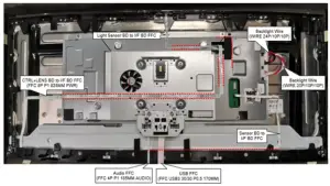
- Remove USB FFC and Audio FFC from USB BD
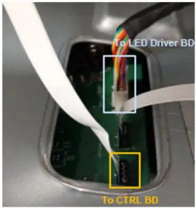
- Remove 1 tape on LED Driver BD wire from Main SHD and disconnect LED Driver BD wire from I/F BDDisconnect CTRL FFC cable from I/F BD and tear it from Main SHDTake off Rear Cover
- Remove all tapes from cables and Rear Cover
- Remove all cables from LED Driver BDUnlock 1 screw and disassemble LED Driver BD from Rear Cover
- Tear off “MYLAR HEAD LOGO” from cover LOGO LENSDisconnect LED wire from LED BDDisassemble LED BD from Rear Cover
- Tear off RC Mylar from USB BD and Jack BD
- Remove 2 tapes on Jack BD from Rear CoverDisassemble Jack BD from Rear CoverRemove 2 wires from Jack BDUnlock 2 screws to disassemble USB BD from Rear Cover
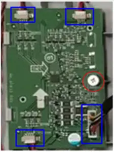
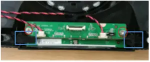
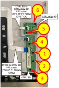
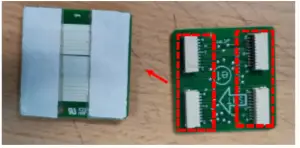
- Remove FFC cable from Rear Cover, CTRL BD and CTRL+KEY BDUnlock 6 screws to disassemble CTRL BD and CTRL+KEY BD from Rear Cover
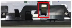
- Take off 1 gasket from Middle Frame
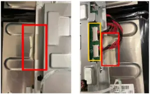
- Disconnect Backlight Wires from SPS+LED BDTear off conductive cloth from Main SHD
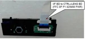
- Disconnect Light Sensor BD FFC cable from I/F BD and tear off it from Main SHDDisconnect Sensor BD FFC cable from I/F BD and tear off it from panelDisconnect “CTRL+LENS BD FFC” from I/F BD and tear off it from panel and Main SHD
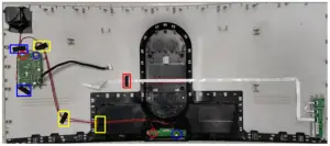
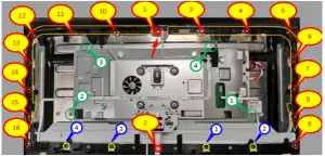
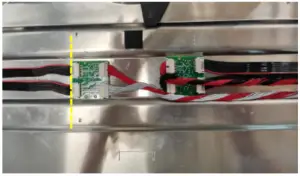
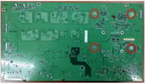
- Unlock 4 screws (Green mark) to disassemble Main SHD from panelUnlock 16 screws (Red mark) and 4 screws (Yellow mark) to disassemble Middle Frame from Panel(Screw Torque-Main SHD: 7±1kgf)(Screw Torque-Middle Frame: 4.5±0.5 kgf)
- Tear off a yellow tape and an acetate tape from EDP cable and panelDisconnect EDP cable from PanelTake off Main SHD from Panel
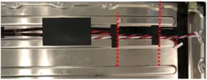
- Tear off a mylar and 2 tapes from Backlight wires
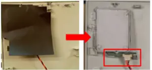
- Disconnect Backlight wires from transfer BD
- Disassemble transfer BD from Panel
- Disassemble Light Sensor BD from Middle Frame
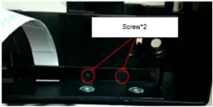
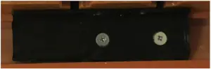
- Unlock 2 screws to disassemble Power Button module from Middle Frame(Screw Torque: 1.1±0.1 kgf)
- Disconnect FFC cable from “CTRL+LENS BD” (Power CTRL BD)
- Tear off “MYLAR-PWR-KE “ from “CTRL+LENS BD” (Power CTRL BD)
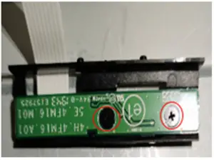
- Unlock 2 screws to disassemble “CTRL+LENS BD” (Power CTRL BD) from Power Button(Screw Torque: 2±0.5 kgf)
- Disassemble Sensor BD from Middle frame
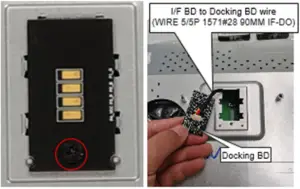
- Unlock 1 screw to disassemble Docking BD from Main SHDDisassemble wire from Docking BD(Screw Torque: 8.5±1.0 kgf)
- Disassemble mylar from Main SHD
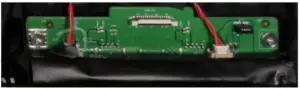
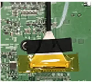
- Tear off an adhesive tape and a yellow tape from I/F BD and EDP cableDisconnect EDP cable from I/F BD
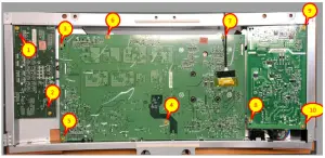
- Unlock 11 screws on PCBA to disassemble SPS+LED BD, SPS BD and I/F BD from Main SHD(Screw Torque: 8.5±1.0 kgf)
- Disconnect wires from I/F BD, SPS BD and SPS+LED BD
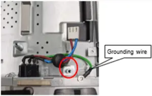
- Unlock 1 ground screw to disassemble AC Socket from Main SHD(Screw Torque: 8-10 kgf)
- Disconnect Fan Cable from I/F BD
- Unlock 4 screws to disassemble GSYNC Module from I/F BD(Screw Torque: 4-4.5 kgf)
- Unlock 4 Heat Sink screws and 4 captive screws to disassemble G-Sync module, Heat Sink Module and SHEET STIFFENERTear off MYLAR from SHEET STIFFENER(Screw Torque-Heat Sink: 2-2.5 kgf)(Screw Torque-Captive screw:4-4.5 kgf)
-
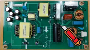
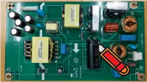
- Remove electrolyte capacitors (red mark) from printed circuit boards
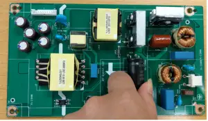
- S38-1 Cut the glue between bulk cap. and PCB with a knife
- S38-2 Ensure cutting path within the glue, don’t touch bulk cap. or PCB
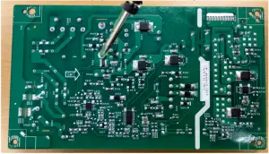
- S38-3 Take out bulk cap. pin solder with soldering iron and absorber
- S38-4 Lift the bulk cap. up and away from the PCB
- Remove electrolyte capacitors (red mark) from printed circuit boards
 (Screw Torque: 8-10 kgf)
 (Screw Torque-Main SHD: 7±1kgf)(Screw Torque-Middle Frame: 4.5±0.5 kgf)
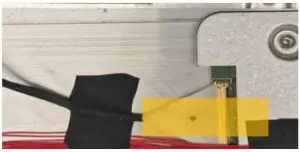
 (Screw Torque: 2±0.5 kgf)
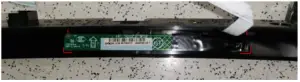
 (Screw Torque: 8.5±1.0 kgf)
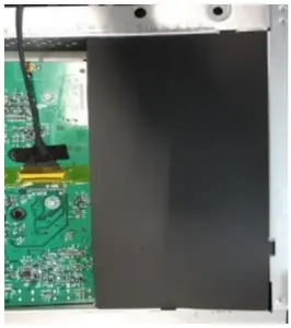
 (Screw Torque: 8.5±1.0 kgf)
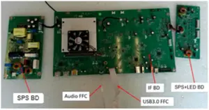
 (Screw Torque: 8-10 kgf)
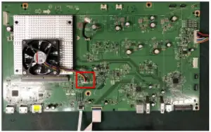
 (Screw Torque: 4-4.5 kgf)
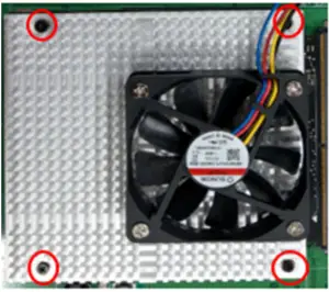 (Screw Torque-Heat Sink: 2-2.5 kgf)
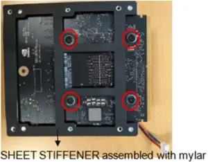 (Screw Torque-Captive screw:4-4.5 kgf)
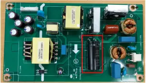
Product material information
The following substances, preparations, or components should be disposed of or recovered separately from other WEEE in compliance with Article 4 of EU Council Directive 75/442/EEC.
| Capacitors / condensers (containing PCB/PCT) | No used |
| Mercury containing components | No used |
| Batteries | No used |
| Printed circuit boards (with a surface greater than 10 square cm) | Product has printed circuit boards (with a surface greater than 10 square
cm) |
| Component contain toner, ink and liquids | No used |
| Plastic containing BFR | No used |
| Component and waste contain asbestos | No used |
| CRT | No used |
| Component contain CFC, HCFC, HFC and HC | No used |
| Gas discharge lamps | No used |
| LCD display > 100 cm2 | Product has an LCD greater than 100 cm2 |
| External electric cable | Product has external cables |
| Component contain refractory ceramic fibers | No used |
| Component contain radio-active substances | No used |
| Electrolyte capacitors (height
> 25mm, diameter > 25mm) |
Product has electrolyte capacitors (height >25mm, diameter > 25mm) |
Tools Required
List the type and size of the tools that would typically can be used to disassemble the product to a point where components and materials requiring selective treatment can be removed.
Tool Description:
- Screwdriver
- Scraper Bar
- Penknife
- Soldering iron and absorber
- Curve Sponge Jig
[xyz-ips snippet=”download-snippet”]