Chapter 8-TEARDOWN INSTRUCTION
S1
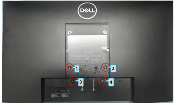
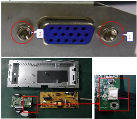
- Remove Rear Cover Screw and Stand Screwsa. Remove screws “1~2” on rear cover with electric screwdriverb. Remove stand screws “3” and “4”. Torque: 12.0 +/- 0.5Kgf/cm

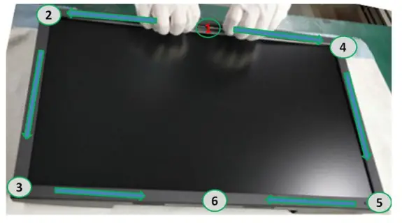
S2 - Remove Front Cover:a. Panel side up, remove the front panel with both hands in a sequence of “1->2->3”, then “1->4->5->6”.
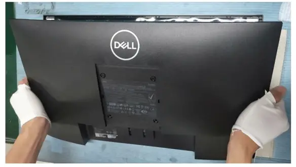
S3 - Remove Rear Cover:a. Turn monitor to rear side up, remove the rear cover.
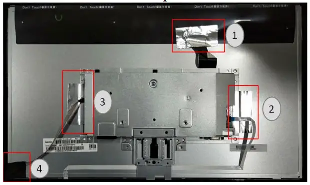
S4 - Remove Aluminium Foil and Acetate Cloth Tapea. Remove aluminium tape in “1~3” orderb. Remove acetate cloth tape marked with “4”
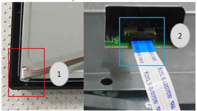
S5 - Remove Light Bar and Keypad Cable:a. Remove light bar “1” (grasp on Pin then pull upwards to remove)b. Remove KP cable “2” (lift cover before removing KP cable)
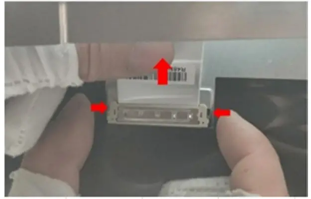
S6 - Remove FFCa. Pinch on clips on the sides, and remove FFCb. Remove assembled chassis from the panel
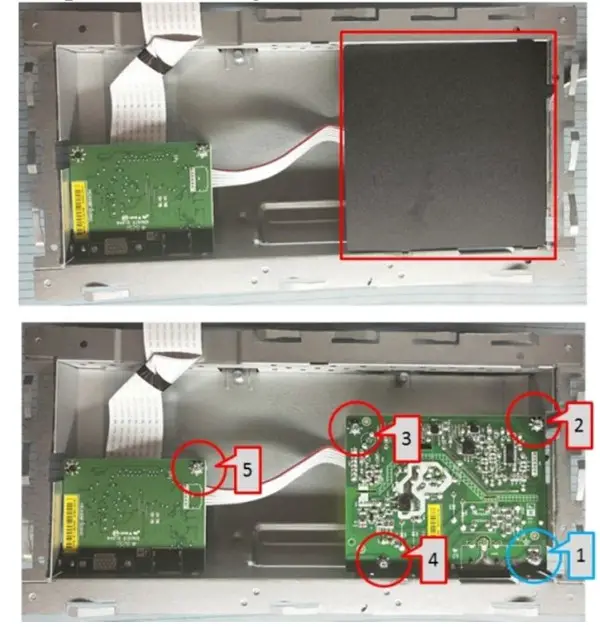
S7 - Remove PCBA 1:a. Remove mylar (squared in red in the upper picture)b. Use electric screwdriver to remove grounding screw “1”, then locking screws marked “2~5”. Screwdriver torque: 5.5±0.5 kg/cm
S8 - Remove PCBA 2:a. Remove 2pcs hex head bolt with electric screwdriverb. Remove IF board and Power boardc. Separate IF board and Powerboard
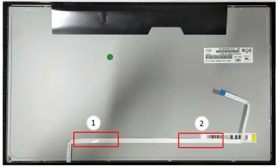
S9 - Separate Front Cover from Panel:a. Tear off Keypad cable from Panel. Taped on “1, 2, 3”.b. Turn the monitor to the front view and remove the front cover.
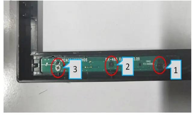
S10 - Remote Keypad:a. Remove screws “1, 2, 3” with electric screwdriver. Screwdriver torque: 1.0±0.1 kgf/cm
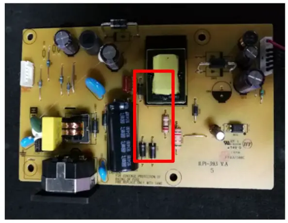
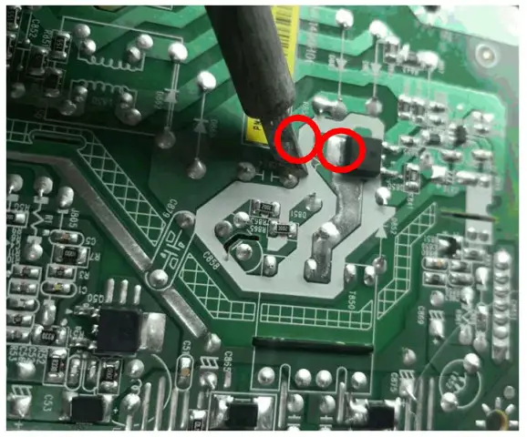
S11a. Remove electrolyte capacitor >25mm height (squared in red) from printed circuit boards.b. Cut the glue between the bulk cap and PCBA with knife ensure cutting path within the glue, don’t touch bulk cap and PCBA.S12a. Take out the capacitor pin solder with a soldering iron.b. Lift the bulk capacitor away from the power board.
- Product Material InformationThe following substances, preparation, or components should be disposed of or recovered separately from other WEEE in compliance with Article 4 of EU Council Directive 75/422/EEC.
Capacitors / Condensers (containing PCB/PCT) Not used Mercury-containing components Not used Batteries Not used Printed circuit boards (with surface greater than 10 square cm) The product has printed circuit boards (with a surface greater than 10 square cm) The component contains toner, ink and liquids Not used Plastic containing BFR Component and waste contain asbestos Not used CRT Not used Component contain CFC, HCFC, HGC and HC Not used Gas discharge lamps Not use LCD display > 100 cm2 Product LCD greater than 100cm2 External electric cable The product has external cables The component contains refractory ceramic fibres Not used The component contains radioactive substances Not used Electrolyte capacitors (height > 25nun, diameter >25mm) Product has electrolyte capacitors (height > 25mm) - Tools RequiredList the type and size of the tools that would typically be used to disassemble the product to a point where components and materials requiring selective treatment can be removed.Tool Description:– Screwdriver (Philip head with 5 mm & 3 mm)– Screwdriver (Hexagonal to remove VGA connectivity)– Soldering iron– Knife
[xyz-ips snippet=”download-snippet”]