![]()
DELL UP3221QB
Disassembly Procedures
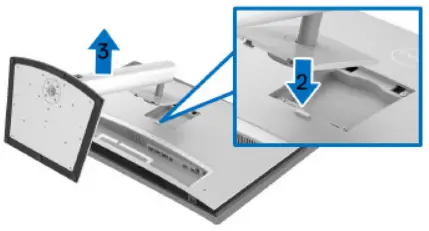
Turn off the monitor.To remove the stand:
Place the monitor on a soft cloth or cushion Press and hold the stand release button Press and lift the cover latch to release and remove the cover
 S1 S2
S1 S2
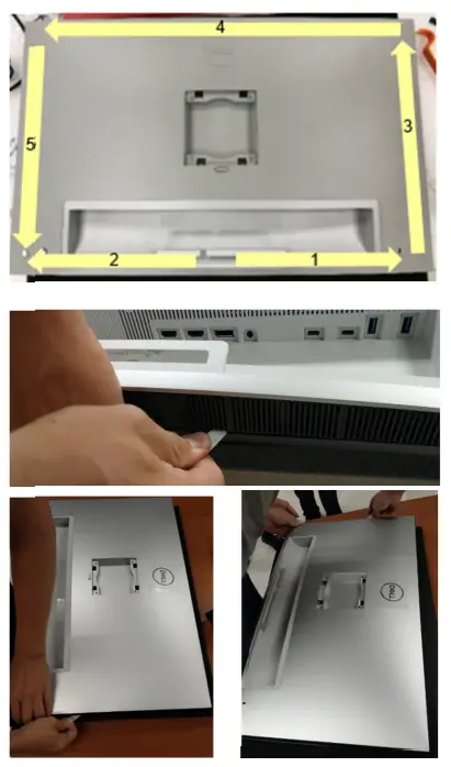
Unlock 2 RC base screws and 4 RC screws to disassemble Rear Cover
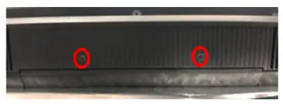 (Screw Torque: 4.5 ± 0.5kgf)
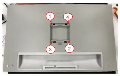 (Screw Torque: 9 ±1kgf)S3
Use hands or scraper bar and follow the sequence to disassemble Rear Cover from Middle Frame
 S4
S4
Disassemble LENS BD from Middle Frame Unplug CTRL BD FFC from LENS BD
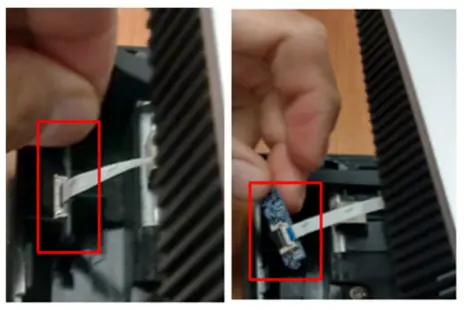 S5
S5
Tear off “MYLAR SHD VESA” from Main SHD and unplug CTRL FFC from I/F BD
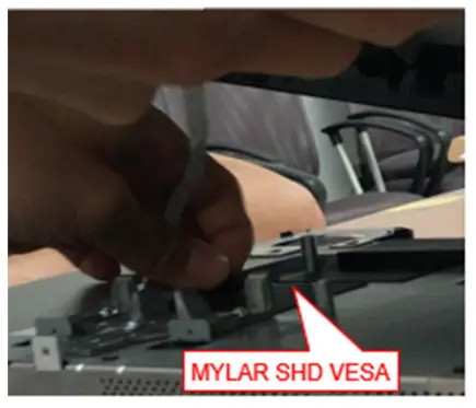 S6
S6
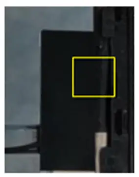
Tear off “MYLAR SHD SOC” from Main SHD and unplug USB FFC from SOC BD Take off Rear Cover from Middle Frame
 S7
S7
Tear off an acetate tape from “Mylar SHD MCU” and Middle Frame
S8
Tear off all mylars from Main SHD
 S9
S9
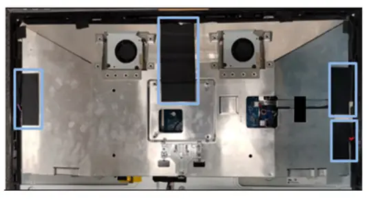
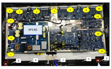
Tear off an acetate tape from Main SHD (See Green mark)Tear off 3 conductive tapes from Main SHD to disassemble “SPS BD wire” from Middle Frame (See Orange mark)Unplug “SPS BD wire” from SPS BD, I/F BD, MCU BD, and TBT BDUnlock screw*10 to disassemble Main SHD from Panel (See Blue mark)
S10(Screw Torque: 4.0-4.5kgf)
Unplug FAN wire from I/F BDTake off Main SHD from Panel
 S11
S11
Tear off 2 yellow tapes from SOC BD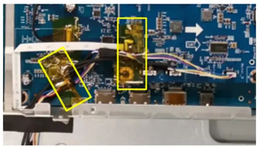
S12
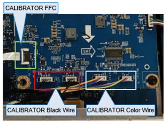
Unplug “CALIBRATOR FFC” from SOC BD (See Green mark)Unplug “CALIBRATOR Color Wire” from SOC BD (See Blue mark)Unplug “CALIBRATOR Black Wire” from SOC BD (See Red mark)
 S13
S13
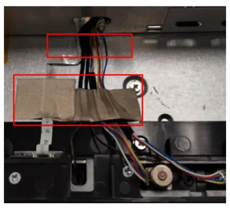
Tear off the tapes from CALIBRATOR wires and PanelTake out all CALIBRATOR wires from the hole of the Main SHD
 S14
S14
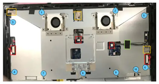
Tear off “CTRL BD GASKET” and “USB GASKET” from Middle FrameUnlock MF screws*13 (See Yellow mark) and TP-S screws*5 (See White Mark)Disassemble Middle Frame to Panel
 S15(Screw Torque: 4.0-4.5kgf)
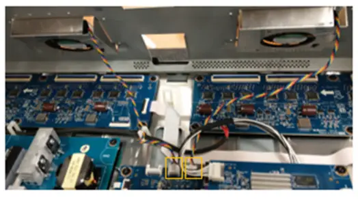
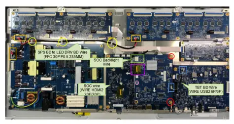
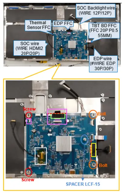
Unplug “SPS BD to LED DRV BD Wire” from SPS BD and LED DRV BD (See Orange mark)Disassemble “SPS BD to LED DRV BD Wire” from the clips (See Yellow mark)Unplug “TBT BD Wire” from “TBT BD” and “SOC BD” (See Blue mark)Unplug “SOC Backlight wire” from “SOC BD” (See Green mark)Tear off a yellow tape and unplug “SOC wire” from “SOC BD” (See Purple mark)Unlock 2 PCBA screws to disassemble “SOC BD” from I/F BD (See Red mark)Disassemble “Short Spacer” from SOC BD (See Pink mark)
S16(Screw Torque: 5.0-5.5kgf)
Unlock 1 grounding screwDisassemble “AC Wire” from “ASSY BKT PLATE
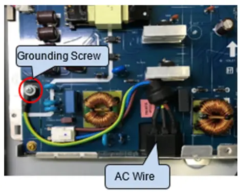
S17(Screw Torque: 5.0-5.5kgf)
Unlock PCBA screw*5 to disassemble SPS BD from “ASSY BKT PLATE”
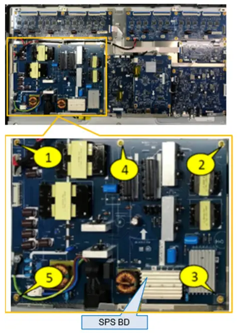
S18(Screw Torque: 5.0-5.5kgf)
Unplug all “Backlight FFC” from LED DRV BDUnplug “Short FFC 30P” from “LED DRV BD (Right)” and “MCU BD”Unplug “Long FFC 30P” from “LED DRV BD(Left)” and “MCU BD
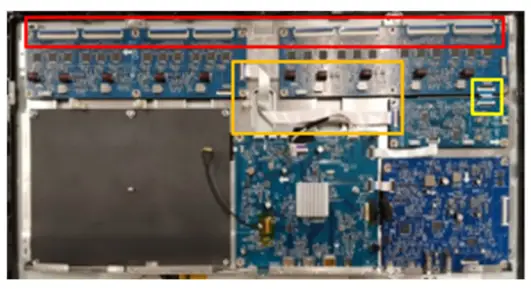
S19
Unlock PCBA screws*12 to disassemble 2 “LED Driver BD” from “ASSY BKT PLATE”
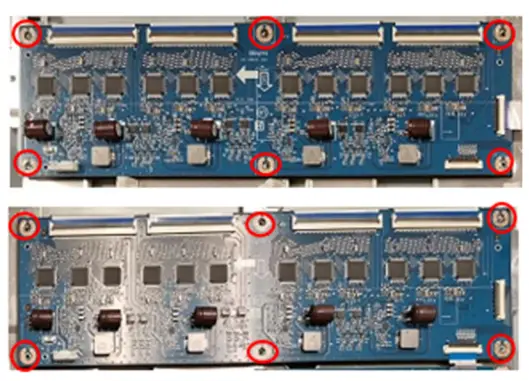
S20(Screw Torque: 5.0-5.5kgf)
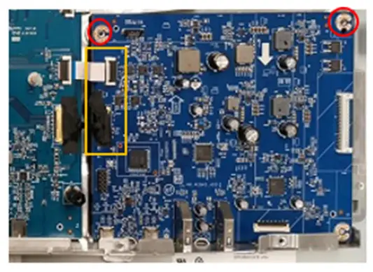
Unplug “MCU BD FFC” from I/F BD and MCU BDUnlock PCBA screw*4 to disassemble “MCU BD” from “ASSY BKT PLATE”
S21(Screw Torque: 5.0-5.5kgf)
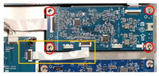
Tear off a tape from EDP wire and TBT BDUnplug “TBT BD FFC” and “EDP wire” from “TBT BD”Unlock PCBA screw*2 to disassemble “TBT BD” from “ASSY BKT PLATE”
S22(Screw Torque: 5.0-5.5kgf)
Tear off a yellow tape from “SOC wire” and I/F BD (See White mark)Unplug “SOC wire” and “SOC Backlight wire” from I/F BDTear off a tape from “EDP FFC” (See Green mark)Unplug “Thermal Sensor FFC” and“EDP FFC” from I/F BD (See Pink mark)Disassemble “Spacer” from I/F BD (SeeBlue mark)Unlock 2 Bolts (See Orange mark) and 2 PCBA screws (See Red mark) from I/FBD to disassemble I/F BD from “ASSY BKT PLATE”Tear off a tape from EDP wire and I/F BD (See Yellow mark)Unplug “TBT BD FFC” and “EDP wire” from I/F BD
S23
Unlock screws*4 to disassemble “ASSY BKT PLATE” from the panelNote:Insert “Thermal Sensor FFC” and “EDP FFC” through the hole of “ASSY BKT PLATE” while disassembling “ASSY BKT PLATE” from Panel
S24
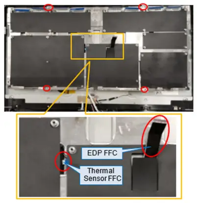
Tear off two tapes from the lower-left corner and lower-right corner of the panel
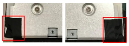
S25
Tear off a yellow tape from EDP FFC and unplug EDP FFC from the panelUnplug all “Backlight FFC” from the panel
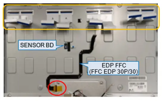 S26
S26
Tear off a tape from Thermal Sensor FFCUnplug Thermal Sensor FFC from Thermal Sensor BD and disassemble Thermal Sensor BD from panel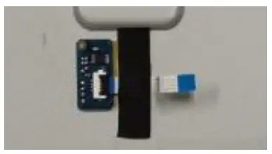
S27
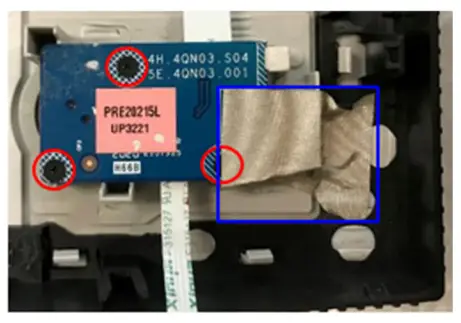
Tear off tapes and “CTRL BD FFC” from Rear Cover
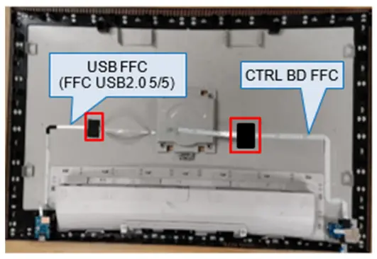
S28
Unlock screw*1 to disassemble USB BD from Rear CoverUnplug “USB FFC” from USB BD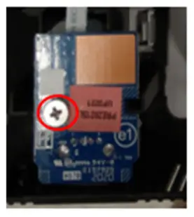
S29(Screw Torque: 4.0-4.5kgf)
Tear off a conductive tape from CTRL BD and Rear CoverUnlock screw*3 to disassemble CTRL BD from Rear Cover
S30(Screw Torque: 1.2-1.3kgf)
Tear off 2 tapes from Main SHD
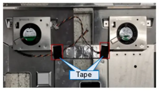
S31
Take out FAN wire from the hole of Main SHD (See Blue mark)
S32
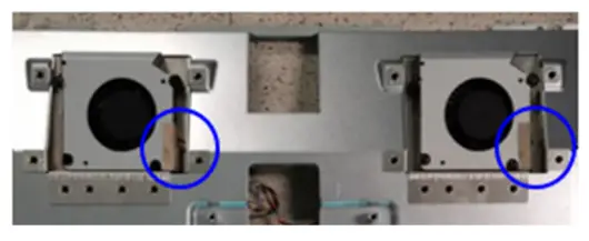
Unlock screws*8 to disassemble FAN from Main SHD
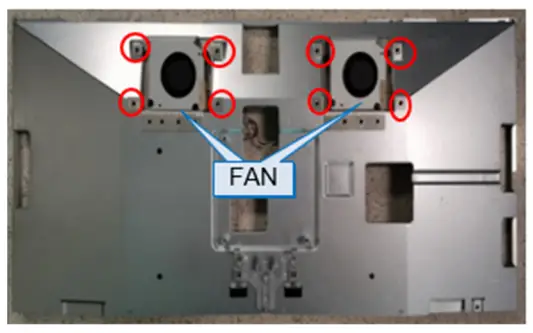
S33
(Screw Torque: 5.0-5.5kgf)
Disassemble Calibrator Cover from Middle Frame.
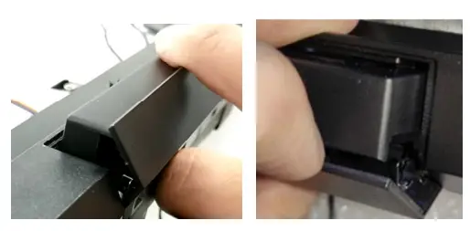
S34
Disassemble “Spring L” and “Spring R” from Calibrator Cover. 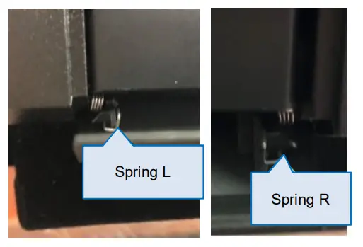
S35
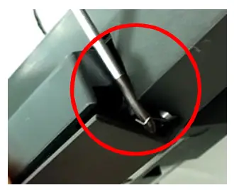
Note: You can use a screwdriver to make a spring unhook from Calibrator Cover.
Take off the Calibrator Cover from the middle frame.
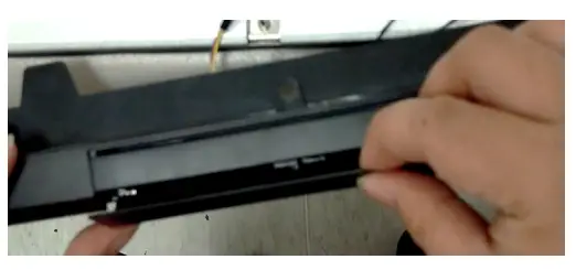
S36
Unlock 6 screws to disassemble CALIBRATOR Module from the middle frame
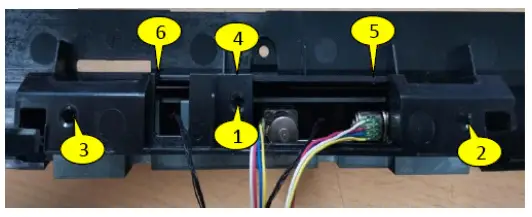
S37
(Screw Torque: 4.5 ±0.5kgf)
Take off CALIBRATOR Module from Middle FrameUnplug “CALIBRATOR FFC Cable” from the CALIBRATOR module
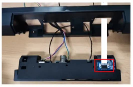
S38
Disassemble “Spring R” and “Spring L” from Middle Frame
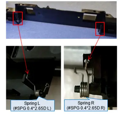
S39
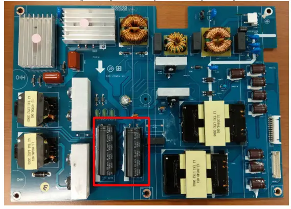
Remove electrolyte capacitors (red mark) from printed circuit boards
S40-1 Cut the glue between bulk cap. and PCB with a knife
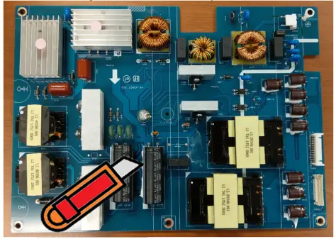
S40-2 Ensure cutting path within the glue, don’t touch bulk cap. or PCB
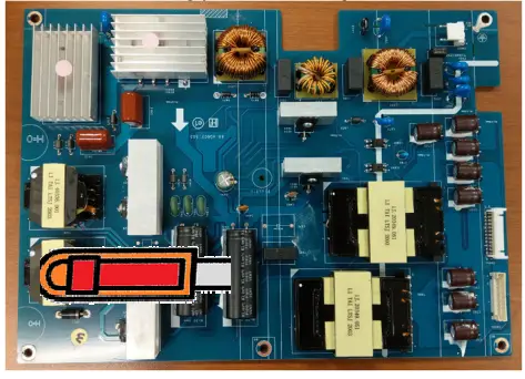
S40-3 Take out bulk cap. pin solder with soldering iron and absorber
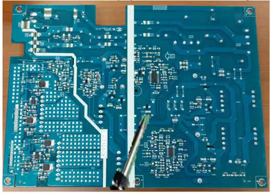
S40-4 Lift the bulk cap. up and away from the PCB
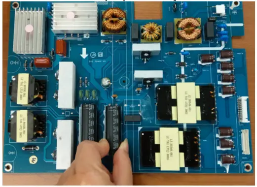
S40
2. Product material informationThe following substances, preparations, or components should be disposed of or recovered separately from other WEEE in compliance with Article 4 of EU Council Directive 75/442/EEC.
| Capacitors / condensers (containing PCB/PCT) | No used |
| Mercury-containing components | No used |
| Batteries | No used |
| Printed circuit boards (with a surface greater than 10 square cm) | The product has printed circuit boards (with a surface greater than 10 square
cm) |
| The component contains toner, ink, and liquids | No used |
| Plastic containing BFR | No used |
| Component and waste contain asbestos | No used |
| CRT | No used |
| Component contain CFC, HCFC, HFC and HC | No used |
| Gas discharge lamps | No used |
| LCD display > 100 cm2 | The product has an LCD greater than 100 cm2 |
| External electric cable | The product has external cables |
| The component contains refractory ceramic fibers | No used |
| The component contains radioactive substances | No used |
| Electrolyte capacitors (height
> 25mm, diameter > 25mm) |
Product has electrolyte capacitors (height >25mm, diameter > 25mm) |
 report this ad
3. Tools RequiredList the type and size of the tools that would typically can be used to disassemble the product to a point where components and materials requiring selective treatment can be removed.Tool Description:– Screwdriver– Scraper Bar– Penknife– Soldering iron and absorber
[xyz-ips snippet=”download-snippet”]