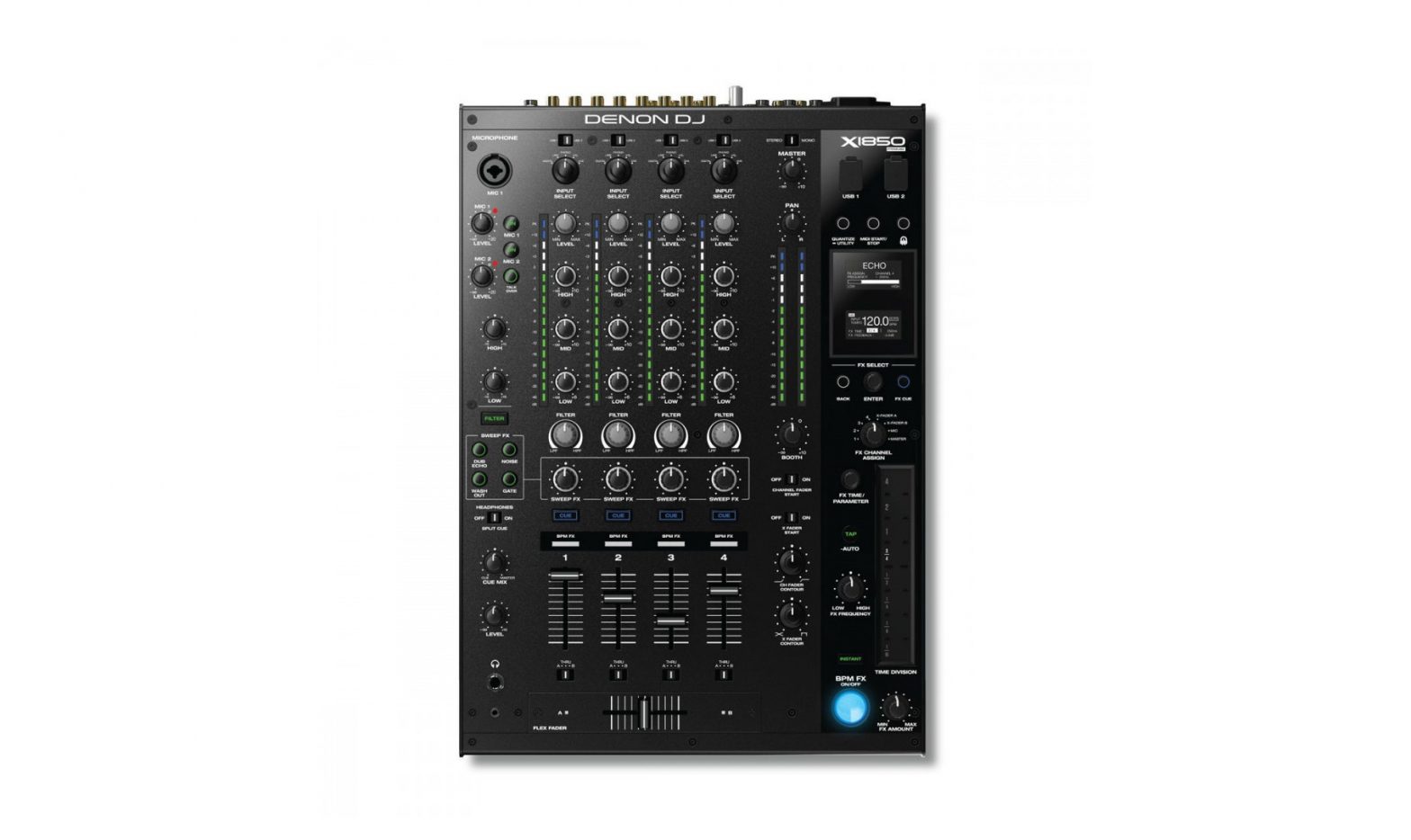
DENON DJ X1850 Prime Professional 4-Channel DJ Club Mixer User Guide
Introduction
Thank you for purchasing the X1850 PRIME. At Denon DJ, we know how serious music is to you. That’s why we design our equipment with only one thing in mind—to make your performance the best it can be. We’re honored and excited to play a part in your musical & creative DJ journey!
Features:
- 4-channel digital mixer with (4) phono/line switchable channels
- BPM FX section with frequency-controlled band isolation
- Dual USB audio connections for software and audio devices
- Dedicated Sweep and BPM FX knobs—high-quality effects, including new Pumper and Echo Hold FX, for each channel with a single knob turn
- FX quantization for FX activation
- Expressive EQ—choose Classic or Isolation modes and an adjustable filter resonance control
- Engine Connect protocol for beatgrid-locked FX
- Expressive Denon DJ Flex-Fader crossfader
- Connect MIDI-based effects and instruments
- 24-bit/96kHz digital output for uncompromised audio quality
- Crisp OLED screen for precise menu-based adjustments
- (4) digital inputs for high-resolution audio mixing
- LAN hub for up to four players or accessories
- Rugged metal construction
- Locking IEC power connection
Box Contents
- X1850 PRIME
- User Guide
- USB Cable
- Safety & Warranty Manual
- Power Cable
Support
For the latest information about this product (documentation, technical specifications, system requirements, compatibility information, etc.), visit denondj.com. For additional product support, visit denondj.com/support.
Product Registration
Your product may include exclusive software and/or promotions which can only be accessed by registering your new product on the Denon DJ website.
To check eligibility and access the available content, please register your product by following the instructions below:
- Visit denondj.com.
- Click Sign In to access your existing account or to create a new account.
- Once signed in, click My Registered Products.
- Enter the product serial number into the box and click Register Product.
- Upon successful registration, any applicable software downloads, exclusive content, and promotional offers will be shown in your account.
Setup
- Make sure all of your devices are powered off or all of their volume levels are at their minimum positions.
- Connect your media players’ audio outputs to the inputs of X1850 PRIME.
- If you are using compatible Denon DJ media players, connect their Link ports to X1850 PRIME’s Link ports according to one of the following connection diagram examples.
- Connect any other devices (turntables, headphones, power amplifiers, loudspeakers, etc.) to the inputs or outputs of X1850 PRIME.
- Connect all of your devices to power sources.
When starting a session, power on (1) your media players and other input sources, (2) X1850 PRIME, and then (3) output devices.
When ending a session, power off (1) output devices, (2) X1850 PRIME, and then (3) your media players and other input sources.
Connection Diagrams
Items shown but not listed under Introduction > Box Contents are sold separately.
Example 1
Example 2
Networking
You can use X1850 PRIME to network multiple compatible Denon DJ media players together, enabling them to seamlessly share timing and BPM information with X185 PRIME (to synchronize effect tempos) as well as track and user profile data with other media players.
This feature provides many advantages while performing. For instance, if you are using four compatible Denon DJ media players, you can use one of them to browse through all tracks on all devices (USB drives or SD cards) connected to any of those media players. You can then play any of those tracks immediately without having to move a device from one unit to the other.
To network compatible Denon DJ media players together, use the included networking cables to connect each of their Link ports to a Link port (1–4) on the rear panel of your X1850 PRIME.
The Network (Media Status) light on each media player will turn on when it is properly connected to a network. By default, X1850 PRIME is set to detect and configure each compatible Denon DJ media player automatically once you connect their Link ports. The Link port on X1850 PRIME will determine which channels that media player uses. See the scenarios below.
You can also freely assign each media player layer to a specific channel by changing the Engine Connect setting in the Utility menu on X1850 PRIME. See your media player’s User Guide to learnmore about this.
When your media player is connected to Link Port 1 on X1850 PRIME, Layer A will use Channel 1, and Layer B will use Channel 2.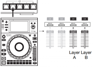 When your media player is connected to Link Port 2 on X1850 PRIME, Layer A will use Channel 2, and Layer B will use Channel 1.
 When your media player is connected to Link Port 3 on X1850 PRIME, Layer A will use Channel 3, and Layer B will use Channel 4.
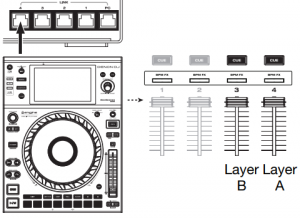 When your media player is connected to Link Port 4 on X1850 PRIME, Layer A will use Channel 4, and Layer B will use Channel 3
Features
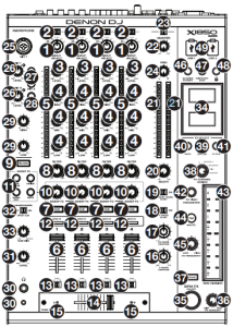
Top Panel
- Input Select: Turn these knobs to select the desired audio source for each channel:
- Digital: When this option is selected, the audio source is the digital ins
- Line: When this option is selected, the audio source is the line inputs
- Phono: When this option is selected, the audio source is the phono inputs
- USB: When this option is selected, the audio source is a computer connected to a USB port
- DVS: When this option is selected, the audio source is a computer connected to a USB port while using control vinyl with a digital vinyl system
- USB 1/2: When the Input Select knob is set to USB, use these switches to select USB Port 1 or USB Port 2 as the source. When a computer is connected to that port, the channel will control the corresponding channel in your software.
- Level: Turn these knobs to adjust the level of the pre-fader, pre-EQ audio signal for each channel.
- EQ (High, Mid, Low): Turn these knobs to boost or cut the high, mid range, and low frequencies for each channel. You can use the Utility menu to set the type of EQ, which determines the minimum (cut) and maximum (boost) values (see Operation > Utility Menu > EQ).
- Channel Level Meters: These LEDs display the audio signal level of each channel, pre-channelfader.
- Channel Fader: Use these faders to adjust each channel’s volume level
- Channel Cue: Press these buttons to send each channel’s pre-fader signal to the headphones’ cue channel. Press more than one of these buttons at the same time to send their channels’ signals to the cue channel simultaneously.
- Filter Knob: Turn these knobs to adjust the filter applied to each channel. Turn the knob counter-clockwise to apply a low-pass filter. Turn the knob clockwise to apply a high-pass filter.
- Filter Button: Press this button to enable or disable the filters (controlled by the Filter knobs) on all channels.
- Sweep FX Knob: Turn these knobs to adjust the balance between the “wet” signal (the sweep effect’s output signal) and “dry” signal (audio without sweep effects applied). Select the center (12:00) position to select an entirely dry signal.
- Sweep FX Buttons: Press one of these buttons to enable or disable an effect that you can control with the Sweep FX knobs. Only one of these buttons can be enabled at a time.
- Dub Echo: This effect is a brief echo. Starting from the center (12:00) position, turn a Sweep FX knob counter-clockwise to decrease the length of the delay and increase the feedback, or turn it clockwise to increase the length of the delay as well as the feedback.
- Noise: This effect adds noise to the signal. Starting from the center (12:00) position, turn a Sweep FX knob counter-clockwise to add white noise with a time-based gate effect synchronized with the channel’s tempo, or turn it clockwise to add whitenoise.
- Wash Out: This creates a transition effect. Turn a Sweep FX knob to its most counterclockwise (minimum) position to apply a 1/2-beat echo that will also mute the channel’s normal audio signal, or turn it to its most clockwise (maximum) position to apply a 1-beat echo.
- Gate: This effect applies a time-based gate effect to the signal. Starting from the center (12:00) position, turn a Sweep FX knob counter-clockwise to apply a gate effect synchronized with the channel’s tempo, or turn it clockwise to apply a gate effect that attenuates the signal. The farther clockwise the knob is turned, the greater the attenuation.12. BPM FX Indicators: These lights will illuminate to indicate if a channel is selected and being affected by the BPM effect module when the FX Channel Assign knob is set to Channel 1, 2, 3, or 4; X-Fader A or B (if the channel is assigned to the active side); or Master (all channels).
- Crossfader Assign: Routes the audio playing on the corresponding channel to either side of the crossfader—A (left) or B (right)—or bypasses the crossfader and sends the audio directly to the program mix—Thru (center).
- Crossfader: Use this crossfader to mix between the active decks.
- Crossfader Indicators: These lights will illuminate to indicate if a side of the crossfader is selected and being affected by effects module (when the FX Channel Assign knob is set to XFader A or B).
- X Fader Contour: Turn this knob to adjust the slope of the crossfader. Turn the knob to the left for a smooth fade (mixing) or to the right for a sharp cut (scratching). The center position is a typical setting for club performances.
- Ch Fader Contour: Turn this knob to adjust the volume slope of the channel faders. Turn the knob counter-clockwise to have the volume get louder “later” (closer to the top of the fader). Turn it clockwise to have the volume get louder “earlier” (almost immediately after moving the fader from its minimum position). The center position is a linear volume increase.
- X Fader Start: Use this switch to enable or disable crossfader start. When enabled, you can automatically start playback on compatible Denon DJ media players assigned to each side of the crossfader by moving the crossfader toward that side.
- Channel Fader Start: Use this switch to enable or disable channel fader start. When enabled, you can automatically start playback on compatible Denon DJ media players connected to each channel by moving the channel fader upward.
- Booth: Turn this knob to adjust the volume level of the booth outputs.
- Master Level Meters: These LEDs display the audio signal level of the master mix (sent out of the master outputs).
- Master: Turn this knob to adjust the volume level of the master outputs.
- Stereo/Mono Selector: Use this switch to set the channel configuration of the master outputs: Stereo (binaural audio using separate left and right channels) or Mono (summed monaural audio through both left and right channels).
- Pan: Turn this knob to adjust the position of the master outputs’ signal in the stereo field.
- Mic 1 Input: Use a standard XLR or 1/4” (6.35 mm) cable (not included) to connect a standard dynamic microphone to this input. Use the Mic 1 Level knob on the top panel to control the volume level.
- Mic 1/2 Level: Turn these knobs to adjust the volume levels of the corresponding microphone inputs. The light next to each knob indicates the current signal level by its color: green (normal/optimal), orange (mid level) or red (maximum/peak).
- Mic On/Off: Press these buttons to activate or deactivate the corresponding microphone.
- Talk Over: Press this button to activate or deactivate the “talk over” feature, which automatically reduces the volume level of the master mix when you speak into the microphone. You can use the Utility menu to set how much the master mix volume level is lowered and how quickly it returns to its normal level (see Operation > Utility Menu > Microphone).
- Mic EQ (High, Low): Turn these knobs to boost or cut the high and low frequencies for both microphones.
- Headphone Outputs: Connect headphones to these 1/4” (6.35 mm) or 1/8” (3.5 mm) jacks for monitoring the signal. Turn the Headphone Level knob to control the volume.
- Headphone Level: Turn this knob to adjust the volume of the headphones.
- Split Cue: When this switch is in the On position, the headphone audio will be “split” such that all channels sent to cue channel are summed to mono and sent to the left headphone channel and the master mix is summed to mono and sent to the right channel. When the switch is in the Off position, the cue channel and master mix will be “blended” together.
- Cue Mix: Turn this knob to adjust the balance between the cue output and the master mix output in the headphones.
- Displays: These displays provide instant feedback about effects parameters, tempo and more. The displays also show the Utility menu, where you can configure hardware settings and change feature behaviors to match your preferred workflow by adjusting audio signal routing, effects module order, input and output levels, and more.
- BPM FX On/Off: Press this button to turn the BPM effect module on or off.
- FX Amount: Turn this knob to adjust the amount of output signal from the BPM effect module.
- Instant: Press this button to enable or disable Instant FX Mode for the FX touch strip.
- FX Channel Assign: Turn this knob to select the channel to which the BPM effect module will apply its effects: Channel 1, 2, 3, or 4; X-Fader A or B (either side of the crossfader); Mic (both microphone signals); or Master (the master mix).
- FX Select/Enter: Turn this knob to select an effect. While in the Utility menu, turn this knob to select an option, and press it to confirm your choice or enter a submenu.
- Back: Press this button to return to the previous screen in the Utility menu.
- FX Cue: Press this button to preview the BPM effects in the headphones’ cue channel. Not all BPM effects can be previewed, though.
- FX Time/Parameter: Turn this knob to select the rate that the BPM effect module will use. Press the knob to switch between adjusting the rate as a time division and the rate in milliseconds. (A corresponding light along the FX touch strip will illuminate to indicate the current time division.) This knob will also adjust other FX parameters when available.
- FX Touch Strip: When the Instant button is off (disabled), tap an area of this touch-capacitive strip to select the time division that the BPM effect module will use. A corresponding light along the strip will illuminate to indicate the current time division. If the current time division is not a quantization value shown on the strip (e.g., the BeatBreak effect), then none of the lights will illuminate. When the Instant button is on (enabled), tap and hold your finger on the strip to activate the effects, and then drag your finger up or down to adjust the time division of the effect.
- Tap/-Auto: Tap this button at least 3 times at the desired tempo to set the rate of the BPM effect module for the channel set by the FX Channel Assign knob (the module’s rate for other channels will remain unchanged). The Tap button will be dimly lit when using a BPM manually entered this way. Press and hold this button for 1 second to synchronize the rate of BPM effect module with the audio signal of the channel set by the FX Channel Assign knob (the module’s rate for other channels will remain unchanged). The Tap button will be brightly lit when using a BPM automatically detected this way, and Auto will be shown next to the BPM in the second display. If you are using a compatible Denon DJ media player with Engine Connect, the media player will control the BPM effect module, and the Engine logo will be shown in the second display.
- FX Frequency: Turn this knob to select a frequency band of the audio signal to which the BPM effects will be applied. Select the center (12:00) position to apply effects to the entire spectrum of frequencies.
- Quantize/-Utility: Press this button to quantize the BPM FX to media players connected to the Link ports. Press and hold this button to enter or exit the Utility menu, which will appear in the display. Exiting the Utility menu also saves any changes you made.
- MIDI Start/Stop: Press this button to send a MIDI Start or MIDI Stop message out of the USB port or MIDI output (you can use the Utility menu to select one). The tempo will be that of the selection of the FX Channel Assign knob. If you change the selection of the FX Channel Assign knob, press and hold this button to send the new tempo.
- Engine Connect: When the Link ports are connected to compatible Denon DJ media players, press this button to enable X1850 PRIME to receive timing and BPM information (to synchronize effect tempos) and to send track and user profile data between media players. Press and hold this button to show the manual channel assignment on the displays of compatible media players.
- USB Ports: Use standard USB cables to connect computers to these USB ports
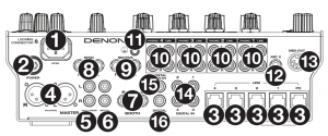
Rear Panel
- Power Input: Use the included locking power cable to connect this input to a power outlet. To remove the power cable, push down on the yellow tab and then pull the cable out of the input. You can also use a standard IEC power cable in place of the included locking power cable
- Power Button: Press this button to power X1850 PRIME on or off. Power on X1850 PRIME only after you have connected all of your input devices and before you power on your amplifiers and loudspeakers. Power off your amplifiers and loudspeakers before powering off X1850 PRIM
- Link Ports: Use standard networking cables to connect these ports to your compatible Denon DJ media players and/or to your computer. Each networked media player can use these connections to share timing and BPM information with X1850 PRIME (to synchronize effect tempos) as well as track and user profile data with other media players.
- Master Outputs (balanced XLR): Use standard XLR cables to connect thes outputs to loudspeakers or an amplifier system. Use the Master knob on the top panel to control the volume level. 10
- Master Outputs (unbalanced RCA): Use standard RCA cables to connect these outputs to loudspeakers or an amplifier system. Use the Master knob on the top panel to control the volume level.
- Record Outputs (RCA): Use standard RCA cables to connect these outputs to a recording interface, external mixer, or other device. Use the Utility menu to select whether or not the mix sent to these outputs will include the microphones’ audio signal (see Operation > Utility Menu > Microphone).
- Booth Outputs (1/4”/6.35 mm, TRS): Use standard 1/4”/6.35 mm cables to connect these outputs to booth monitors or a booth amplifier system. Use the Booth knob on the top panel to control the volume level. Use the Utility menu to select whether or not the mix sent to theseoutputs will include the microphones’ audio signal (see Operation > Utility Menu > Microphone).
- Send Outputs (1/4”/6.35 mm, TRS): Connect these outputs to the inputs of an external effects module or other device.
- Receive Inputs (1/4”/6.35 mm, TRS): Connect these inputs to the outputs of an external effectsmodule or other device. You can use the Utility menu to set the level of this audio signal (see Operation > Utility Menu > FX).
- Phono/Line Inputs (RCA): Use standard RCA cables to connect these line level or phono-level inputs to an external audio source. Use the input selectors on the top panel to set whether the signal from the line-level inputs or phono-level inputs will be sent to each channel.
- Grounding Terminal: If you are using phono-level turntables with a grounding wire, connect the grounding wire to this terminal. If you experience a low “hum” or “buzz”, this could mean that your turntables are not grounded.Note: Some turntables have a grounding wire built into the RCA connection and, therefore, nothing needs to be connected to the grounding terminal.
- Mic 2 Input (1/4”/6.35 mm, TRS): Use a standard 1/4” (6.35 mm) cable (not included) to connecta standard dynamic microphone to this input. Use the Mic 2 Level knob on the top panel to control the volume level.
- MIDI Output (5-pin DI ): Use a standard MIDI cable to connect this output to the MIDI input of an optional external MIDI device. You can use the MIDI Send button to send MIDI Start messages from this output. You can also use the Utility menu to enable or disable this connection (see Operation > Utility Menu > System).
- Digital In (digital RCA): Use digital RCA cables to connect these 24-bit/96 KHz inputs to the digital outputs of your compatible Denon DJ media players.
- Digital Link In (digital RCA): If you are using more than one X1850 PRIME unit, use a digital RCA cable to connect this input to the digital out of another X1850 PRIME.
- Digital Out (digital RCA): Use a digital RCA cable to connect this output to the digital input of another X1850 PRIME unit or an external interface, mixer, or other device. Use the Utility menu to set the level of the outgoing signal (see Operation > Utility Menu > Advanced Audio).
Operation
Effects
BPM Effect Module
The built-in effect module enables you to apply any one of several effects to specific channels based on its”current tempo.
To turn the BPM effect module on or off, press BPM FX On/Off.
To select the channel to which the BPM effect module will apply its effects, turn the FX Channel Assign knob. The options are: Channel 1, 2, 3, or 4; X-Fader A or B (either side of the crossfader); Mic (both microphone signals); or Master (the master mix).
To apply or remove the effect to or from the cue channel, press FX Cue. When the button is lit, effects will be applied to the headphones’ cue channel only.
To select an effect, turn the FX Select/Enter knob. These are the available effects:
- To select an effect, turn the FX Select/Enter knob. These are the available effects:
- Echo: This effect adds echoes of the original signal. Use the FX Parameter knob to set the Feedback level of the echo effect.
- Delay: This effect adds repeated instances of the original signal that decay over time.
- Hall Echo: This effect adds a combination of reverb and echo. Use the FX Parameter knob to set the Decay level of the echo effect.
- Ping Pong: This is a stereo delay effect where the rate of delay is different between the left and right channels.
- Auto Gate: This effect cuts off the original signal at a regular rate.
- Flanger: This effect adds a slightly delayed copy of the original signal to create a comb-filter effect (often referred to as resembling a jet plane engine).
- Filter: This effect varies the filter cutoff frequency at a regular rate.
- Phaser: This effect adds a copy of the original signal with its phase shifted slightly to create a subtle, modulatory effect.
- Bit Crush: This effect adds a low bit-rate filter. Use the FX Parameter knob to set the Bit Average and Bit Depth to change the sound of the effect.
- Reverb: This effect adds reverberation to the original signal. The amount of delay depends on the tempo. Use the FX Parameter knob to adjust the Decay of the reverb, and press the FX Parameter knob while the reverb is active to “freeze” the reverb and kill the channel audio.
- Roll: This effect samples the current audio signal and repeats it at a regular rate based on the current time division.
- RevRoll (reverse roll): This effect samples the current audio signal and repeats it backward at a regular rate based on the current time division.
- BeatBreak: This effect samples the 4 beats of each bar of the original signal and replays them (within the same bar) according to a preset pattern, creating a “stuttering,” “breakbeat” effect.
To select a pattern to use, turn the FX Time knob to select Pattern 0–15, as shown in the second display. The 16 blocks ( █ ) and/or lines ( __ ) below it indicate the rhythm of the current pattern similar to a drum machine’s step sequencer: a block represents a “hit”/”strike” and a line represents a rest.
Examples:
ndicates a hit on each beat.indicates a hit on every 8th note.indicates a hit on every 16th note (every note of the pattern).
Use the Utility menu to edit the patterns (see Utility Menu > FX).
- Scratch: This effect alternates between normal and reverse playback of each beat, creating a vinylscratching effect.
- Pumper: This effect attenuates or “ducks” audio on the downbeat, similar to a sidechain compressor. The available parameters are:
- Duck: Sets the volume attenuation: -2dB to -20dB.
- Offset: Sets the ducking offset time in beats: -1/16, -1/8, -1/4 or -1/2.
- Echo Hold: This effect applies an echo that, when the FX Amount knob is turned clockwise past the center point, hold repeats on the last echo. Turn the FX Amount Knob back counter-clockwise past the center point to remove the echo hold.
- SendRtn (send/return): This option will enable the send outputs and receive inputs, allowing you to use external effects on the signal.
All of the BPM effects are time-based, so the BPM effect module offers several ways for you enter or detect the tempo it will use.
To adjust the time division of the BPM effect module, do either of the following:
- Make sure the time division (__ Beat) is selected in the lower display (if it is not, press the FX Time knob), and then turn the FX Time knob to select another time division.
- When the Instant button is off, tap an area of the FX touch strip to select a time division. A corresponding light along the strip will illuminate to indicate the current time division.
- To adjust the rate of the BPM effect module in milliseconds, make sure the millisecond rate (__ ms) is selected in the lower display (if it is not, press the FX Time knob), and then turn the FX Time knob to adjust it.
To enter a new tempo, press Tap at least 3 times at the desired tempo. This will set the rate of the BPM effect module for the channel set by the FX Channel Assign knob (the module’s rate for other channels will remain unchanged). The Tap button will be dimly lit when using a BPM manually entered this way.
To detect the tempo automatically, press and hold Tap/-Auto for 1 second. This will synchronize the rate of the BPM effect module with the audio signal of the channel set by the FX Channel Assign knob (the module’s rate for other channels will remain unchanged). The Tap button will be brightly lit when using a BPM automatically detected this way, and Auto will be shown next to the BPM in the second display.Note: If you are using a compatible media player with Engine Connect, the media player will control the BPM effect module, and the Engine logo will be shown in the second display.
To adjust the tempo manually, press and hold Tap/-Auto, and then turn the FX Time knob to adjust the BPM in increments of 1. While still holding Tap/-Auto, press and turn the FX Time knob to adjust the BPM in increments of 0.1.
To enable FX quantization, use the FX Quantize setting in Utility Menu > FX. When enabled, BPM FX will activate starting on a beat or beat increment using the beat grid of a compatible media player.
You can easily change the amount of FX signal to adjust the balance between the “wet” signal (the BPM effect module’s output signal) and “dry” signal (audio without effects applied).
To adjust the balance between the “wet” and “dry” signals, turn the FX Amount knob. Alternatively, use the FX touch strip while in Instant FX Mode (see below).
Normally, you would apply effects to the entire frequency spectrum, but X1850 PRIME also lets you apply them to an isolated frequency band of the audio signal (of the selected channel).
To select the frequency band, turn the FX Frequency knob. Select the center (12:00) position to apply effects to the entire spectrum of frequencies.
Instant FX Mode allows you to use the FX touch strip to activate the effect and adjust its time division simultaneously.
To enable or disable Instant FX Mode, press Instant. The button will light up when it is enabled.
To activate the effect, tap and hold your finger on the FX touch strip, and then drag your finger up or down to adjust the time division of the effect.
Sweep FX
Sweep FX allows you to apply one of four effects to the four channels and “sweep” them using the Sweep FX knobs. You can apply only one sweep effect at a time
To activate a sweep effect, tap one of the Sweep FX buttons: Dub Echo, Noise, Wash Out, or Gate. The button will light up when activated. Only one of these buttons can be enabled at a time.
To deactivate a sweep effect, tap the lit Sweep FX button. Alternatively, press a different Sweep FX button to activate it, which will deactivate the other.
For all sweep effects, the center (“12:00”) position of the Sweep FX knob bypasses the effect. Turning the Sweep FX knob clockwise or counter-clockwise from this position applies the effect, and can produce different results in each direction depending on the type of effect. The available sweep effects and their functions are as follows:
- Dub Echo: This effect adds a brief echo. Turn a Sweep FX knob counter-clockwise to decrease the length of the delay and increase the feedback, or turn it clockwise to increase the length of the delay as well as the feedback.
- Noise: This effect adds noise to the signal. Turn a Sweep FX knob counter-clockwise to add white noise with a time-based gate effect synchronized with the channel’s tempo, or turn it clockwise to ad white noise.
- Wash Out: This creates a transition effect. Turn a Sweep FX knob to its most counter-clockwise (minimum) position to apply a 12-beat echo that will also mute the channel’s normal audio signal, or turn it to its most clockwise (maximum) position to apply a 1-beat echo.
- Gate: This effect applies a time-based gate effect to the signal. Turn a Sweep FX knob counterclockwise to apply a gate effect synchronized with the channel’s tempo, or turn it clockwise to apply a gate effect that attenuates the signal. The farther clockwise the knob is turned, the greater the attenuation.
The Utility menu enables you to customize various settings on X1850 PRIME that affect the audio signal routing, effects module, input and output levels, and more.
To enter or exit the Utility menu, press and hold Quantize/-Utility. Exiting the Utility menu also saves any changes you made.
While in the Utility menu, you can do any of the following:
- To select an option, turn the FX Select/Enter knob.
- To confirm your choice or enter a submenu, press the FX Select/Enter knob.
- To return to the previous screen, press Back.
Below are descriptions of the different submenus in the Utility menu:
EQ
These settings determine how the Channel EQ knobs work.
- Type: Select ISO to set the Channel EQ knobs’ ranges to -∞ to +6dB/+10dB (as labeled). Select EQ to set the Channel EQ knobs’ ranges to -24dB to +6dB (for other players that may need this setting).
- High Cross Over: This is the crossover frequency between the High and Mid EQ knobs when the Type is set to ISO: 1000Hz–8000Hz (in varying increments).
- Low Cross Over: This is the crossover frequency between the Mid and Low EQ knobs when the Type is set to ISO: 100Hz–800Hz (in varying increments).
- Reset EQ Default: Select OK to return these Channel EQ settings to their default values, or select Cancel to return to the previous menu.
Filter
- Resonance: This is the resonance of the filters on Channels 1–4 (i.e., how much the frequencies just beyond the cutoff frequency are allowed to pass through the filter). 0 is a flat setting (frequencies just beyond the cutoff frequency won’t be heard at all), while 15 yields a high resonance (the cutoff frequency is not as “strict,” so some adjacent frequencies will be heard).
- Extreme Type: This setting determines the effect of the Sweep Filters at the extreme low and high ends. Select Kill for the filter extremes to end in silence, or select Bleed to allow the extreme end of the filter to play.
Headphone
- Attenuation: This is the gain level of the headphone output: -10dB to +10dB.
- Split Cue Output: This sets which side of the stereo signal plays the Cue program on headphones, Left or Right.
Microphone
These settings affect the microphones.
- Attenuation: This is the gain level of the microphone inputs: -15dB to +0dB.
- Gate Threshold: This setting changes the amount of audio required to engage the mic signal. Different types of microphones may require this to be adjusted for best use: -40dB to -79dB.
- Talk Over Level: This setting determines how much the master mix volume level is lowered when the microphone talkover feature is activated: -40dB to -20dB.
- Talk Over Resume: While using the talkover feature, the master mix volume will return to its normal level after the microphoe input detects no incoming signal. This setting determines whether that transition occurs moderately (Normal) or quickly (Fast).
- EQ High: This is the frequency band that will be affected by the High Mic EQ knob: 1,000Hz– 10,000Hz (in varying increments).
- EQ Low: This is the frequency band that will be affected by the Low Mic EQ knob: 100Hz–900Hz (in varying increments).
- Booth Receive: Select On to allow the microphone signal to be sent to the booth outputs and record outputs. Select Off to send the microphone signal to the master outputs only.
- Headphone Receive: Select On to allow the microphone signal to be sent to the headphones. Select Off to send the microphone signal to the master outputs only.
- Reset Mic Default: Select OK to return the Mic settings to their default values, or select Cancel to Nreturn to the previous menu.
FX
These settings affect the FX on X1850 PRIME.
- FX Return: This is the unity level for the send outputs and receive inputs: -10dB–+10dB. You may need to adjust this setting based on the types of external effects you are using.
- Beat Break Edit: This menu enables you to select, edit, and store patterns for the BeatBreak effect. See Effects > BPM Effect Module for more information about how this effect works.
To edit a pattern:
- Turn the FX Select/Enter knob to select a pattern (1–16), and then press it.
- Turn the FX Select/Enter knob to select one of 12 16th-notes in the pattern. You cannot edit the four main beats of the pattern; they will always sound because they contain the audio being sampled. Press the FX Select/Enter knob to change the beat from a “hit”/“strike” ( █ ) to a rest ( __ ) or viceversa.Repeat this step, if desired.
- Press Back to return to the previous screen.
- FX List Customize: Use this screen to customize the order of effects. Turn the FX Select/Enter knob to select an effect from the list of available ones on the left side, and then press the knob to add the effect to the new order on the right side. Repeat this step for each effect, or select -Cancel- to return to the previous screen. After you have done this for all effects, select -End- to save your customized list.
- BPM FX On Color: This setting determines the color of the BPM FX On/Off button while it flashes: red, spring green, green, light blue, blue, yellow, orange, or purple.
- Noise Level: This setting determines the level of noise when using the Noise Sweep FX: -20dB to +15dB.
- FX Quantize: This setting determines the amount of time FX will wait before turning on after the BPM FX button is activated: 1, 1/2, 1/4, or 1/8 beat. This will keep the FX in time with the beat grid of connected media players.
- FX Limiter: Turn this setting On to limit the volume of the FX output so it is equal to the input from the channel. Select Off to apply no limiter to the FX.
Advanced Audio
These settings determine the mixer’s digital operation and other advanced functions.
- Sampling Rate: This is the sampling rate of the USB audio signal: 44.1kHz, 48kHz, or 96kHz.
- Master Out Level: This is an offset to the volume level of the master outputs: -15dB to 0dB.
- Master Limiter: This applies a limiter to the master output: 20dB to 0dB. Select Off to apply no limiter to the master output.
- Booth Settings: These settings determine the routing for booth audio:
- Booth Pan: This setting determines whether the booth audio can be panned along with the master audio (Enable) or not (Disable).
- Booth Out Level: This is an offset to the volume level of the booth: 0dB to -15dB.
- USB Audio: These settings determine the routing and levels of USB audio.
- CH1–4/Master/Cue Assign: These settings determine which USB audio channels (1/2–9/10) will receive the audio signal from Channels 1–4 (CH1–CH4), and the master mix (Master).
- Output Level: This is an offset to the volume level of the master mix sent to your computer over a USB connection: -20dB to +20dB.
- Ch Input Level: This is an offset to the volume level of the audio signals sent to Channels 1–4 from your computer over a
- USB connection: -20dB to +20dB.
- Broadcast Mode: When set to On, this option allows you to send the master signal to your computer over USB audio channels 1–2 for use with broadcasting software. Set to Off to disable Broadcast Mode.Note: When Broadcast Mode is enabled, a message will appear to indicate that DVS on Channel 1 will be disabled. Press Enter to continue.
- DVS Setup: For Channels 1–4 (CH1–CH4), select the input level each one will use when its input selector is set to DVS. Select Phono to use control vinyl records or Line to use control CDs.
- Digital Settings:
- Digital Out: This is an offset to the volume level of the audio signal sent from the digital out: -20dB to +20dB.
- Digital Link: Select On to sum the outgoing signal before the Master knob and Booth knob, which you can use to control their output level. Select Off to sum the outgoing signal after the Master knob and Booth knob, which will have no effect on the output level.
- Link Level: This is an offset to the volume level of the audio signal sent to the Digital Link In: -20dB to +20dB.
- Cross Fader Cut: These settings determine how far you must move the crossfader from each side (Fader Cut A or B) for it to start affecting the audio signal: -2.0mm to 1.0mm
System
These settings determine overall operation.
- Info: These screens contain information about the current firmware version and network information.
- Version: This is the current X1850 PRIME firmware version.
- IP Address: This is the IP address that X1850 PRIME is using.
- MAC Address: This is the MAC address that X1850 PRIME is using.
- Hardware: This is the current hardware version.
- Display:
- Display Brightness: This setting changes the brightness of the OLED display: Low, Med, or High.
- LED Brightness: This setting changes the brightness of all LEDs on the control surface: Low, Med, or High.
- • Engine Connect: Select Auto to enable X1850 PRIME to automatically receive timing and BPM information (to synchronize effect tempos) from compatible media players connected to its Link ports and to send track and user profile data between them. X1850 PRIME will also automatically detect and configure each media player once you connect their Link ports. Select Manual to disable automaticlinking and only activate this feature manually by pressing and holding the Engine Connect button until the Channel Assignment screen appears on the media players. You can then freely assign each media player layer to a specific channel.
- Cue Settings:
- Cue Solo Mode: Select On to use the Channel Cue buttons as “solo” buttons (pressing one will mute all other channels). Select Off to use them as normal cue buttons (pressing one will send its signal to the cue channel).
- Inactive Cue State: This setting determines the off state of the Cue LEDs: DIM or Off.
- Cue 1–4 Color: This setting determines the color of the Cue buttons for each channel: red, spring green, green, light blue, blue, yellow, orange, or purple.
- Reset Cue Defaults: Select OK to return the Cue settings to their default values, or select Cancel to return to the previous menu.
- Contour Lock: When set to On, this setting locks the Crossfader Contour to the current knob position so it is not changed if the knob is moved. Set to Off to disable the lock.
- Through Position Lock: When set to On, this setting locks the Crossfader Assign switches to the Thru position so it is not changed if the switch is moved. Set to Off to disable the lock.
- Network Settings:
- Refresh IP Address: Select OK to renew your IP address, which reestablishes the connection
- between your X1850 PRIME and any compatible Denon DJ media players connected to the Link ports. Select Cancel to return to the previous screen.
- MIDI: These are MIDI settings that determine how the MIDI connections are used.
- Clock Send: These settings determine whether or not X1850 PRIME will send MIDI Clock messages over each of these connections. For each option, select On to enable transmission or Off to disable it.
- USB: This applies to both USB Ports 1 and 2. If you are using X1850 PRIME to control software, set this to On.
- 5pin: This applies to the MIDI out.
- Active Send: These sttings determine whether or not X1850 PRIME will send normal MIDI messages over each of these connections. For each option, select On to enable transmission or Off to disable it.
- USB: This applies to both USB Ports 1 and 2. If you are using X1850 PRIME to control software, set this to On.
- 5pin: This applies to the MIDI out.
- Factory Reset: Select OK to restore X1850 PRIME to its factory default settings (wait a few seconds after selecting this before resuming normal operation). Select Cancel to return to the previous screen.
References
[xyz-ips snippet=”download-snippet”]