

Heavy-Duty Compact Router DWP610/DWP611

SAVE ALL WARNINGS AND INSTRUCTIONS FOR FUTURE REFERENCE
The term “power tool” in the warnings refers to your mains-operated (corded) power tool or battery-operated (cordless) power tool.
- WORK AREA SAFETYa) Keep work area clean and well lit. Cluttered or dark areas invite accidents.b) Do not operate power tools in explosive atmospheres, such as in the presence of flammable liquids, gases or dust. Power tools create sparks which may ignite the dust or fumes.c) Keep children and bystanders away while operating a power tool. Distractions can cause you to lose control.
- ELECTRICAL SAFETYa) Power tool plugs must match the outlet. Never modify the plug in any way. Do not use any adapter plugs with earthed (grounded) power tools. Unmodified plugs and matching outlets will reduce risk of electric shock.b) Avoid body contact with earthed or grounded surfaces such as pipes, radiators, ranges and refrigerators. There is an increased risk of electric shock if your body is earthed or grounded.c) Do not expose power tools to rain or wet conditions. Water entering a power tool will increase the risk of electric shock.d) Do not abuse the cord. Never use the cord for carrying, pulling or unplugging the power tool. Keep cord away from heat, oil, sharp edges or moving parts. Damaged or entangled cords increase the risk of electric shock.e) When operating a power tool outdoors, use an extension cord suitable for outdoor use. Use of a cord suitable for outdoor use reduces the risk of electric shock.f) If operating a power tool in a damp location is unavoidable, use a ground fault circuit interrupter (GFCI) protected supply. Use of a GFCI reduces the risk of electric shock.
- PERSONAL SAFETYa) Stay alert, watch what you are doing and use common sense when operating a power tool. Do not use a power tool while you are tired or under the influence of drugs, alcohol or medication. A moment of inattention while operating power tools may result in serious personal injury.b) Use personal protective equipment. Always wear eye protection. Protective equipment such as dust mask, non-skid safety shoes, hard hat, or hearing protection used for appropriate conditions will reduce personal injuries.c) Prevent unintentional starting. Ensure the switch is in the off position before connecting to power source and/or battery pack, picking up or carrying the tool. Carrying power tools with your finger on the switch or energising power tools that have the switch on invites accidents.d) Remove any adjusting key or wrench before turning the power tool on. A wrench or a key left attached to a rotating part of the power tool may result in personal injury.e) Do not overreach. Keep proper footing and balance at all times. This enables better control of the power tool in unexpected situations.f) Dress properly. Do not wear loose clothing or jewellery. Keep your hair, clothing and gloves away from moving parts. Loose clothes, jewelery or long hair can be caught in moving parts.g) If devices are provided for the connection of dust extraction and collection facilities, ensure these are connected and properly used. Use of dust collection can reduce dust-related hazards.
- POWER TOOL USE AND CAREa) Do not force the power tool. Use the correct power tool for your application. The correct power tool will do the job better and safer at the rate for which it was designed.b) Do not use the power tool if the switch does not turn it on and off. Any power tool that cannot be controlled with the switch is dangerous and must be repaired.c) Disconnect the plug from the power source and/or the battery pack from the power tool before making any adjustments, changing accessories, or storing power tools. Such preventive safety measures reduce the risk of starting the power tool accidentally.d) Store idle power tools out of the reach of children and do not allow persons unfamiliar with the power tool or these instructions to operate the power tool. Power tools are dangerous in the hands of untrained users.e) Maintain power tools. Check for misalignment or binding of moving parts, breakage of parts and any other condition that may affect the power tool’s operation. If damaged, have the power tool repaired before use. Many accidents are caused by poorly maintained power tools.f) Keep cutting tools sharp and clean. Properly maintained cutting tools with sharp cuttingedges are less likely to bind and are easier to control.g) Use the power tool, accessories and tool bits etc., in accordance with these instructions taking into account the working conditions and the work to be performed. Use of the power tool for operations different from those intended could result in a hazardous situation.
- SERVICEa) Have your power tool serviced by a qualified repair person using only identical replacement parts. This will ensure that the safety of the power tool is maintained.
Additional Specific Safety Rules
- Hold power tools by insulated gripping surfaces when performing an operation where the cutting tool may contact hidden wiring or its own cord. Contact with a “live” wire will make exposed metal parts of the tool “live” and shock the operator.
- Use clamps or another practical way to secure and support the workpiece to a stable platform. Holding the work by hand or against your body leaves it unstable and may lead to loss of control.
- DO NOT cut metal.
- Keep handles and gripping surfaces dry, clean, and free from oil and grease. This will enable better control of the tool.
- Maintain firm grip with both hands on router to resist starting torque.
- Keep hands away from cutting area. Never reach under the workpiece for any reason. Keep the router base firmly in contact with the workpiece when cutting. These precautions will reduce the risk of personal injury.
- Never run the motor unit when it is not inserted in one of the router bases. The motor is not designed to be handheld.
- Keep cutting pressure constant. Do not overload motor.
- Check to see that the cord will not snag or impede the routing operation.
- Use sharp cutters. Dull cutters may cause the router to swerve or stall under pressure.
- Be sure that the motor has stopped completely before you lay the router down. If the cutter head is still spinning when the tool is laid down, it could cause injury or damage.
- Be sure that the router bit is clear of the workpiece before starting the motor. If the bit is in contact with the workpiece when the motor starts it could make the router jump, causing damage or injury.
- ALWAYS disconnect tool from power source before making adjustments or changing bits.
- Keep hands clear of bit when motor is running to prevent personal injury.
- NEVER touch the bit immediately after use. It may be extremely hot.
- Provide clearance under workpiece for router bit when through-cutting.
- Tighten collet nut securely to prevent the bit from slipping.
- Never tighten collet nut without a bit.
- Do not use router bits with a diameter in excess of 1-3/8″ (34.9 mm) in this tool.
- Always use cutters with a shank diameter of 1/4″ (6.4 mm) which corresponds to the size of the collet in your tool.
- Always use cutters suitable for a speed of min. 27,000 min-1 and marked accordingly.
- Not recommended for use in a router table.
- Avoid climb-cutting (cutting in direction opposite that shown in Figure 12). Climb-cutting increases the chance for loss of control resulting in possible injury. When climb-cutting is required (backing around a corner), exercise extreme caution to maintain control of router. Make smaller cuts and remove minimal material with each pass.
- An extension cord must have adequate wire size (AWG or American Wire Gauge) for safety. The smaller the gauge number of the wire, the greater the capacity of the cable, that is 16 gauge has more capacity than 18 gauge. An undersized cord will cause a drop in line voltage resulting in loss of power and overheating. When using more than one extension to make up the total length, be sure each individual extension contains at least the minimum wire size. The following table shows the correct size to use depending on cord length and nameplate ampere rating. If in doubt, use the next heavier gauge. The smaller the gauge number, the heavier the cord.
| Minimum Gauge for Cord Sets | ||||||
|
Ampere Rating |
Volts | Total Length of Cord in Feet (meters) | ||||
| 120V | 25 (7.6) | 50 (15.2) | 100 (30.5) | 150 (45.7) | ||
| 240V | 50 (15.2) | 100 (30.5) | 200 (61.0) | 300 (91.4) | ||
| More
Than |
Not More Than | AWG | ||||
| 0 | 6 | 18 | 16 | 16 | 14 | |
| 6 | 10 | 18 | 16 | 14 | 12 | |
| 10 | 12 | 16 | 16 | 14 | 12 | |
| 12 | 16 | 14 | 12 | Not Recommended |
WARNING: ALWAYS use safety glasses. Everyday eyeglasses are NOT safety glasses. Also use face or dust mask if cutting operation is dusty. ALWAYS WEAR CERTIFIED SAFETY EQUIPMENT:
- ANSI Z87.1 eye protection (CAN/CSA Z94.3),
- ANSI S12.6 (S3.19) hearing protection,
- NIOSH/OSHA/MSHA respiratory protection.
- lead from lead-based paints,
- crystalline silica from bricks and cement and other masonry products, and
- arsenic and chromium from chemically-treated lumber.
Your risk from these exposures varies, depending on how often you do this type of work. To reduce your exposure to these chemicals: work in a well ventilated area, and work with approved safety equipment, such as those dust masks that are specially designed to filter out microscopic particles.
Avoid prolonged contact with dust from power sanding, sawing, grinding, drilling, and other construction activities. Wear protective clothing and wash exposed areas with soap and water. Allowing dust to get into your mouth, eyes, or lay on the skin may promote absorption of harmful chemicals.
SAVE THESE INSTRUCTIONS
Motor
Be sure your power supply agrees with nameplate marking. 120 Volts AC means your tool will operate on alternating current. As little as 10% lower voltage can cause loss of power and can result in overheating. All DEWALT tools are factory-tested; if this tool does not operate, check the power supply.WARNING: Accessories must be rated for at least the speed recommended on the tool warning label. Accessories running over rated speed can fly apart and cause injury. Accessory ratings must always be above tool speed as shown on tool nameplate.WARNING: To reduce the risk of injury, turn unit off and disconnect it from power source before installing and removing accessories, before adjusting or when making repairs. An accidental start-up can cause injury.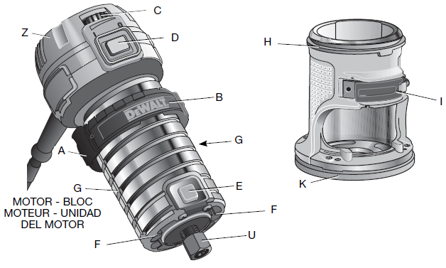
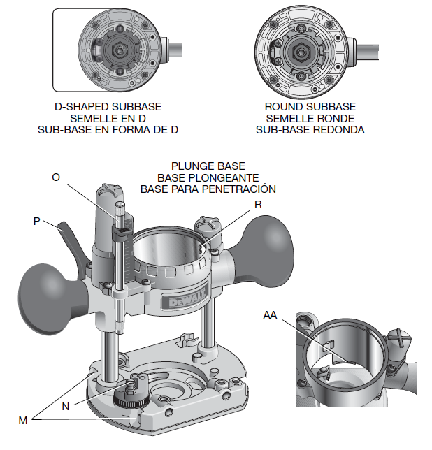
A. Quick release tabsB. Depth adjustment ringC. Variable speed dial(DWP611 only)D. On(l)/off (o) switchE. Spindle lock buttonF. Led lights (DWP611 only)G. Guide pin grooveH. Micro adjustment scaleI. Locking leverJ. Edge guide slot (fixed base)K. Subbase(DWP610 has a round subbase, DWP611 has a D-subbase) both are available as an accessory.L. Vacuum attachment(For use with plunge base)M. Holes for premium edge guide (sold separately)N. Turret stopO. Depth adjustment rodP. Plunge lock leverQ. Edge guideR. Guide pinsS. Locking lever adjustment screwT. Centering toolU. Collet nutV. Vacuum attachment (fixed base)W. Screws (vacuum attachment)X. Edge guide slot (plunge base)Z. Motor unitAA. Motor stopBB. Thumb screwCC. Knurled knobDD. Depth adjustment scaleEE. Zero adjuster tabFF. Sub-base screwsGG. Edge guide screwsHH. Tab (vacuum attachment)II. Snap tab (vacuum attachment)JJ. Plastic washer (vacuum attachment)KK. Thumb screw (vacuum attachment)
OPERATION
WARNING: To reduce the risk of injury, turn unit off and disconnect it from power source before installing and removing accessories, before adjusting or when making repairs. An accidental start-up can cause injury.NOTICE: Do not use router bits with a diameter in excess of 1-3/8″ (34.9 mm) in this tool.
Connecting To Power Source
CAUTION: Before connecting tool to power source, check to see that the switch is in the “OFF” position. Also, check the power circuit to see that it is the same as that shown on specification plate of the tool.Starting and Stopping the Motor (Fig. 1)CAUTION: Before starting the tool, clear the work area of all foreign objects. Also keep firm grip on tool to resist starting torque.CAUTION: To avoid personal injury and/or damage to finished work, always allow the power unit to come to a COMPLETE STOP before putting the tool down.To turn unit on, depress the side of the dust-protected switch (D) that reads “ON” and corresponds to the symbol “I.” To turn the unit off, depress the side of the switch that reads “OFF” and corresponds with the symbol “O.”
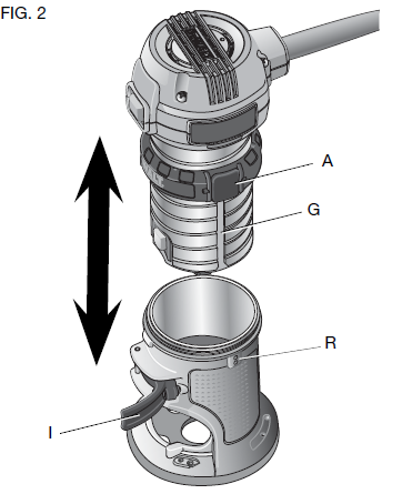
Motor Quick Release
WARNING: To reduce the risk of injury, turn unit off and disconnect it from power source before installing and removing accessories, before adjusting or when making repairs. An accidental start-up can cause injury.
- Open the locking lever (I) on the base.
- Grasp the motor unit with one hand, depressing both quick release tabs (A).
- With the other hand, grasp the base and pull motor from the base.
TO INSTALL THE BIT
- Remove the motor unit from the base unit, see Motor Quick Release (if needed).
- Clean and insert the round shank of the desired router bit into the loosened collet as far as it will go and then pull it out about 1/16″ (1.6 mm).
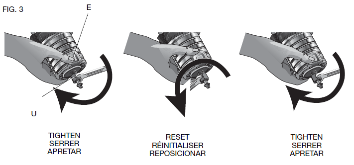
- Depress the spindle lock button (E) to hold the spindle shaft in place while turning the collet nut (U) clockwise with the wrench provided.NOTE: The unit is equipped with multiple spindle lock detents allowing an optional “manual ratchet” method of tightening the bit.To tighten with the “manual ratchet” method:a. Without removing the wrench from the collet nut (U), release pressure on the spindle lock button (E).b. With the wrench still on the collet nut (U), reverse the tightening direction to reset the wrench position.c. Depress the spindle lock button (E) again and turn the wrench clockwise.d. Repeat the procedure until the collet nut (U) reaches desired tightness.
NOTICE: Avoid possible damage to the collet. Never tighten the collet without a bit.
TO REMOVE THE BIT
- Remove the motor unit from the base unit, see Motor Quick Release.
- Depress the spindle lock button (E) to hold the spindle shaft in place while turning the collet nut (U) counterclockwise with the wrench provided.To loosen using the “manual ratchet” method:
- Without removing the wrench from the collet nut (U), release pressure on the spindle lock button (E).
- With the wrench still on the collet nut (U), reverse the loosening direction to reset the wrench position.
- Depress the spindle lock button (E) again and turn the wrench counterclockwise.
- Repeat the procedure until the collet nut (U) is loose and the bit can be removed.
Collets
NOTE: Never tighten the collet without first installing a router bit in it. Tightening an empty collet, even by hand, can damage the collet.To change collet sizes, unscrew the collet assembly as described above. Install the desired collet by reversing the procedure. The collet and the collet nut are connected. Do not attempt to remove the collet from the collet nut.
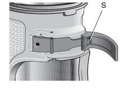
Locking Lever Adjustment
WARNING: To reduce the risk of injury, turn unit off and disconnect it from power source before installing and removing accessories, before adjusting or when making repairs. An accidental start-up can cause injury.Excessive force should not be used to clamp the locking lever. Using excessive force may damage the base.When the locking lever is clamped the motor should not move in the base. Adjustment is needed if the locking lever will not clamp without excessive force or if the motor moves in the base after clamping.
To adjust the locking lever’s clamping force:
- Open the locking lever (I).
- Using a hex wrench turn locking lever adjustment screw (S) in small increments.Turning the screw clockwise tightens the lever, while turning the screw counterclockwise loosens the lever.
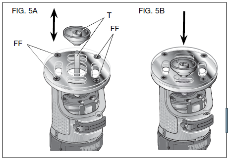
Centering the Subbase
To reduce the risk of injury, turn unit off and disconnect it from power source before installing and removing accessories, before adjusting or when making repairs. An accidental start-up can cause injury.
If you need to adjust, change, or replace the subbase, a centering tool is recommended, refer to Accessories. The centering tool consists of a cone and a pin.To adjust the subbase, follow the steps below.
- Loosen but do not remove the subbase screws (FF) so the subbase moves freely.
- Insert the pin into the collet and tighten the collet nut.
- Insert the motor into the base and clamp the locking lever on the base.
- Place the cone on the pin (Fig. 5A) and lightly press down on the cone until it stops as shown in Figure 5B. This will center the subbase.
- While holding down on the cone, tighten the subbase screws.
Using Template Guides
The round subbase will accept universal template guides. Recommended accessories for use with your tool are available at extra cost from your local dealer or authorized service center.
NOTE: The D-shape subbase does not accommodate template guides and is designed to accommodate bits up to 1-3/8″ (34.9mm) in diameter.To use Template Guides:
- Center the subbase. See Centering The Subbase.
- Install template guide (available as an accessory) on the subbase and tighten securely.
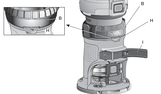
Adjusting the Depth of Cut
To reduce the risk of injury, turn unit off and disconnect it from power source before installing and removing accessories, before adjusting or when making repairs. An accidental start-up can cause injury
- Select and install the desired bit. See Bit Installation and Removal.
- Assemble base to motor, ensuring base is attached to the depth adjustment ring. Place router on the work piece.
- Open the locking lever (I) and turn the depth adjustment ring (B) until the bit just touches the work piece. Turning the ring clockwise raises the cutting head while turning it counterclockwise lowers the cutting head.
- Turn the micro adjustable scale (H) clockwise until the 0 on the scale lines up with the pointer on the bottom of the depth adjustment ring.
- Turn the depth adjustment ring until the pointer lines up with desired depth of cut marking on the micro adjustable scale.NOTE: Each mark on the adjustable scale represents a depth change of 1/64″ or .015″ (0.4 mm) and one full (360º) turn of the ring changes the depth 0.5″ (12.7mm).
- Close the locking lever (I) to lock the base.
Using an Edge Guide
An edge guide (model DNP618) is available from your local retailer or service center at extra cost.
- Remove the motor unit from the base unit, see Motor Quick Release.
- Remove flat head screws (GG) from storage holes on edge guide.
- Slide edge guide into edge guide slot (J) on side of fixed base or (X) on side of the plunge base. Insert the two flat head screws through the appropriate holes in the sub base to secure the edge guide. Tighten hardware.
- Follow all instructions included with the edge guide.NOTE: To remove the edge guide, reverse the above procedure. After removing edge guide always replace the two flat head screws into the storage holes on the edge guide to prevent loss.
Using a Premium Edge Guide (Plunge Base Only)A Premium Edge Guide (model DW6913) is available from your local retailer or service center at extra cost. Follow the assembly instructions included with the edge guide.
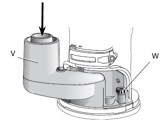
Vacuum Attachment
WARNING: To reduce the risk of injury, turn unit off and disconnect it from power source before installing and removing accessories, before adjusting or when making repairs. An accidental start-up can cause injury.To connect the router to a vacuum cleaner for dust collection, follow these steps:
- Remove the motor unit from the base unit, see Motor Quick Release.
- Attach vacuum attachment accessory (V) to the base as shown. Tighten thumb screws (W) securely by hand.
- Attach hose adapter to vacuum attachment accessory.
- When using vacuum attachment, be aware of the placement of the vacuum cleaner. Be sure that the vacuum cleaner is stable and that its hose will not interfere with the work.
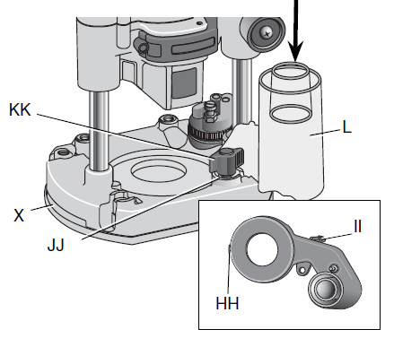
Vacuum Attachment
- Remove the motor unit from the plunge base, see Motor Quick Release.
- Slide tab (HH, inset) on vacuum attachment into slot in plunge base and snap tab (II, inset) into hole in plunge base.
- Secure to base with supplied plastic washer (JJ) and thumb screw (KK). Tighten thumb screw securely by hand.
- Attach hose adaptor to vacuum attachment.
- When using vacuum attachment, be aware of the placement of the vacuum cleaner. Be sure the vacuum cleaner is stable and its hose will not interfere with the work.
Set-up: Fixed Base
INSERTING THE MOTOR INTO THE FIXED BASE
WARNING: To reduce the risk of injury, turn unit off and disconnect it from power source before installing and removing accessories, before adjusting or when making repairs. An accidental start-up can cause injury
- Open the locking lever (I) on the base.
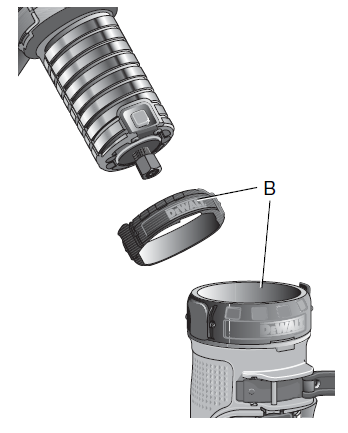
- If the depth adjustment ring (B) is not on the motor, thread the depth adjustment ring (B) onto the motor until the ring is about halfway between the top and bottom of the motor as shown. Insert the motor into the base by aligning the groove on the motor (G) with the guide pins (R) on the base. Slide the motor down until the depth adjustment ring snaps into place.NOTE: Guide pin grooves (G) are located on either side of the motor so it can be positioned in two orientations.
- Adjust the depth of cut by turning the depth adjustment ring. See Adjusting the Depth of Cut.
- Close the locking lever (I) when the desired depth is achieved. For information on setting the cutting depth, see Adjusting the Depth of Cut.
Set-up: Plunge Base

INSERTING THE MOTOR INTO THE PLUNGE BASE
WARNING: To reduce the risk of injury, turn unit off and disconnect it from power source before installing and removing accessories, before adjusting or when making repairs. An accidental start-up can cause injury
- Remove the depth adjustment ring (B) from the motor. It is not used with the plunge base.NOTE: Snap depth adjustment ring onto fixed base, when not in use, to prevent loss.
- Insert the motor into the base by aligning the groove on the motor (G) with the guide pins (R) on the base. Slide the motor down until the motor stops on the motor stop (AA).
- Close the locking lever (I).
ADJUSTING THE PLUNGE ROUTING DEPTH
WARNING: To reduce the risk of injury, turn unit off and disconnect it from power source before installing and removing accessories, before adjusting or when making repairs. An accidental start-up can cause injury
- Unlock the plunge mechanism by pulling down the plunge lock lever (P). Plunge the router down as far as it will go, allowing the bit to just touch the workpiece.
- Lock the plunge mechanism by releasing the plunge lock lever (P).
- Loosen the depth adjustment rod (O) by turning the thumb screw (BB) counterclockwise.
- Slide the depth adjustment rod (O) down so that it meets the lowest turret stop (N).
- Slide the zero adjuster tab (EE) on the depth adjustment rod down so that the top of it meets zero on the depth adjustment scale (DD).
- Grasping the top, knurled section of the depth adjustment rod (O), slide it up so that the tab (EE) aligns with the desired depth of cut on the depth adjustment scale (DD).
- Tighten the thumb screw (BB) to hold the depth adjustment rod in place.
- Keeping both hands on the handles, unlock the plunge mechanism by pulling the plunge lock lever (P) down. The plunge mechanism and the motor will move up. When the router is plunged, the depth adjustment rod will hit the turret stop, allowing the router to reach exactly the desired depth.
USING THE ROTATING TURRET FOR STEPPED CUTS
If the depth of cut required is more than is acceptable in a single pass, rotate the turret so that depth rod (O) lines up with taller turret stop initially. After each cut, rotate the turret so that the depth stop lines up with shorter post until the final depth of cut is reached.WARNING: Do not change the turret stop while the router is running. This will place your hands too near the cutter head.
Operation: All Bases DIRECTION OF FEED
The direction of feed is very important when routing and can make the difference between a successful job and a ruined project. The figures show the proper direction of feed for some typical cuts. A general rule to follow is to move the router in a counterclockwise direction on an outside cut and a clockwise direction on an inside cut.Shape the outside edge of a piece of stock by following these steps:
- Shape the end grain, left to right
- Shape the straight grain side moving left to right
- Cut the other end grain side
- Finish the remaining straight grain edge
CHOOSING ROUTER SPEED (DWP611 AND DWP611PK ONLY) Refer to the Speed Selection Chart to choose a router speed. Turn the variable speed dial (C) to control router speed.SOFT START FEATURE (ALL MODELS)The Compact Routers are equipped with electronics to provide a soft start feature that minimizes the start up torque of the motor.VARIABLE SPEED CONTROL (ALL UNITS)This router is equipped with a variable speed dial (C) with an infinite number of speeds between 16,000 and 27,000 RPM. Adjust the speed by turning the variable speed dial (C).NOTICE: In low and medium speed operation, the speed control prevents the motor speed from decreasing. If you expect to hear a speed change and continue to load the motor, you could damage the motor by overheating. Reduce the depth of cut and/or slow the feed rate to prevent tool damage.The Compact Routers are equipped with electronics to monitor and maintain the speed of the tool while cutting.
SPEED SELECTION CHART
| DIAL SETTING | APPROX. RPM | APPLICATION |
| 1 | 16,000 |
Large diameter bits and cutters |
| 2 | 18,200 | |
| 3 | 20,400 | |
| 4 | 22,600 |
Small diameter bits and cutters. Softwoods, plastics, laminates. |
| 5 | 24,800 | |
| 6 | 27,000 |
Troubleshooting
For assistance with your tool, visit our website at visit www.dewalt.com or call 1-800-4-DEWALT (1-800-433-9258).
MAINTENANCE
WARNING: To reduce the risk of injury, turn unit off and disconnect it from power source before installing and removing accessories, before adjusting or when making repairs. An accidental start-up can cause injury.
Cleaning
WARNING: Blow dirt and dust out of all air vents with dry air at least once a week. Wear proper ANSI Z87.1 (CAN/CSA Z94.3) eye protection and proper NIOSH/OSHA/MSHA respiratory protection when performing this.WARNING: Never use solvents or other harsh chemicals for cleaning the non-metallic parts of the tool. These chemicals may weaken the materials used in these parts. Use a cloth dampened only with water and mild soap. Never let any liquid get inside the tool; never immerse any part of the tool into a liquid.Failure To StartShould your tool fail to start, check to make sure the prongs on the cord plug are making good contact in the outlet. Also, check for blown fuses or open circuit breakers in the line.LubricationThis tool has been lubricated with a sufficient amount of high grade lubricant for the life of the unit under normal operating conditions. No further lubrication is necessary.Brush InspectionFor your continued safety and electrical protection, brush inspection and replacement on this tool should ONLY be performed by a DEWALT factory service center, a DEWALT authorized service center or other qualified service personnel.At approximately 100 hours of use, take or send your tool to your nearest DEWALT factory service center or DEWALT authorized service center to be thoroughly cleaned and inspected. Have worn parts replaced and lubricated with fresh lubricant. Have new brushes installed, and test the tool for performance.
Any loss of power before the above maintenance check may indicate the need for immediate servicing of your tool. DO NOT CONTINUE TO OPERATE TOOL UNDER THIS CONDITION. If proper operating voltage is present, return your tool to the service station for immediate service.
Waxing Motor and Base
To maintain a smooth action when moving the motor unit in relation to the base, the outside of the motor unit and the inside of the base can be waxed using any standard paste or liquid wax. Per the manufacturers instructions, rub the wax onto the outside diameter of the motor unit and the inside diameter of the base. Allow wax to dry and buff off residue with a soft cloth.
Repairs
To assure product SAFETY and RELIABILITY, repairs, maintenance and adjustments (including brush inspection and replacement) should be performed by a DEWALT factory service center, a DEWALT authorized service center or other qualified service personnel. Always use identical replacement parts.
Accessories
WARNING: Since accessories, other than those offered by DEWALT, have not been tested with this product, use of such accessories with this tool could be hazardous. To reduce the risk of injury, only DEWALT, recommended accessories should be used with this product. Recommended accessories for use with your tool are available at extra cost from your local service center.
If you need assistance in locating any accessory, please contact DEWALT Industrial Tool Co., 701 East Joppa Road, Baltimore, MD 21286 or call 1-800-4-DEWALT (1-800-433-9258).
Three Year Limited Warranty
DEWALT will repair, without charge, any defects due to faulty materials or workmanship for three years from the date of purchase. This warranty does not cover part failure due to normal wear or tool abuse. For further detail of warranty coverage and warranty repair information, visit www.dewalt.com or call 1-800-4-DEWALT (1-800-433-9258). This warranty does not apply to accessories or damage caused where repairs have been made or attempted by others. This warranty gives you specific legal rights and you may have other rights which vary in certain states or provinces.
In addition to the warranty, DEWALT tools are covered by our:
1 YEAR FREE SERVICE
DEWALT will maintain the tool and replace worn parts caused by normal use, for free, any time during the first year after purchase.
90 DAY MONEY BACK GUARANTEEIf you are not completely satisfied with the performance of your DEWALT Power Tool, Laser, or Nailer for any reason, you can return it within 90 days from the date of purchase with a receipt for a full refund – no questions asked.LATIN AMERICA: This warranty does not apply to products sold in Latin America. For products sold in Latin America, see country specific warranty information contained either in the packaging, call the local company or see website for warranty information.FREE WARNING LABEL REPLACEMENT: If your warning labels become illegible or are missing, call 1-800-4-DEWALT (1-800-433-9258) for a free replacement.
References
[xyz-ips snippet=”download-snippet”]