![]()
DIGITECH Clamp Meter User Manual
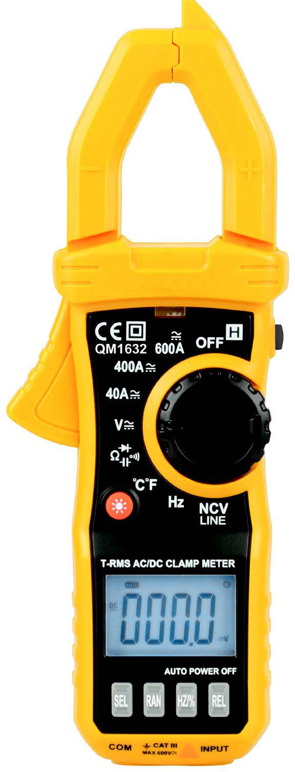
600 Amp AC/DC Clampmeter
Thank you for purchasing this 600 Amp AC/DC Clampmeter. The reading range of up to 600A makes this clampmeter ideal for electrical fitters and contractors working with high currents. Autoranging by default, the clampmeter also features true RMS for accurate readings. Utilise the data hold and relative measurement modes to log and compare data. The backlight will assist you to view various readings in low light conditions.
Please familiarise yourself with the functions of the clampmeter before use. We recommend retaining this manual for ease of reference.
- Improper use of this meter can cause damage, shock, injury or death.
- Always remove the test leads before replacing the battery or fuses.
- Before using the meter, please inspect the condition of the test leads and themeter itself for any damage. If damage is present, please discontinue use.
- Do not measure voltage if the voltage on the terminals exceeds 600V aboveearth ground.
- Use great care if voltages are greater than 30VAC RMS. Anything above thisis considered a shock hazard.
- Do not apply voltage to the meter when the resistance is selected.
- Do not exceed the maximum limits of the input values shown in thespecification tables on pages 10-12 of this manual.
- Remove the batteries from the meter if it will be unused for an extendedperiod of time.
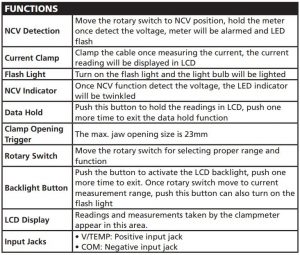
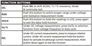
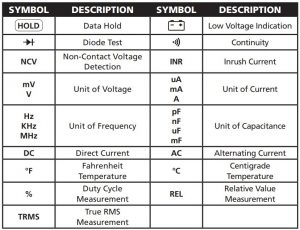
FUNCTIONS
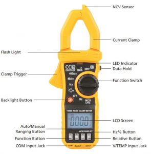
The battery compartment is at the rear of the multimeter.
OPERATING INSTRUCTIONS
NOTE: Read and understand all Warning and Caution statements in this operation manual prior to using this meter. Set the rotary switch to the OFF position when the meter is not in use.
CURRENT MEASUREMENTS
 WARNING:
- Disconnect the test leads before making clamp measurements
- To avoid electrical shock and/or damage to the meter, do not attempt to take any voltage measurement that might exceed 600V
- Set the rotary switch to proper current range, select the correct range based on measurement
- Press the clamp opening trigger to open the jaws and fully enclose one conducting wire
- Read the measured current value in the LCD display
- If display shows “OL”, means overload, should select the higher range of measurements
- To shift the AC or DC current by pressing SEL button
DC VOLTAGE MEASUREMENTS
WARNING:
• The max. input DC voltage is 600V DC, to avoid electrical shock and/or damage the meter, do not attempt to take any voltage measurement that might exceed 600V DC
- Set the rotary switch to the
 position.
 - Insert the black test lead banana plug into COM jack, insert the red test lead banana plug into INPUT jack.
- Touch the black test probe tip to the negative side of the circuit; touch the red test lead probe tip to the positive side of circuit.
- Read the voltage value in the display.
NOTE: Unstable display may occur, especially at the low voltage range measurement (like 200mV range), even no test leads insert at input terminals, and it is the normal situation and not influences the accuracy.
AC VOLTAGE MEASUREMENTS
WARNING:
The max. input DC voltage is 600V DC, to avoid electrical shock and/or damage the meter, do not attempt to take any voltage measurement that might exceed 600V DC
- Set the function switch to the position.
- Insert the black test lead banana plug into COM jack, insert the red test lead banana plug into INPUT jack.
- Touch the black test probe tip to the negative side of the circuit; touch the red test lead probe tip to the positive side of circuit.
- Read the voltage value in the display.
NOTE: Unstable display may occur, especially at the low voltage range measurement (like 2V range), even no test leads insert at input terminals, and it is the normal situation and not influences the accuracy.
RESISTANCE MEASUREMENT
WARNING:
- To avoid electric shock, disconnect power to the unit under test and discharge all capacitors before taking any resistance measurements
- Set the function switch to position and press the SEL button to select the Ω range
- Insert the black test lead banana plug into COM jack, insert the red test lead banana plug into INPUT jack.
- Touch the black test probe tip to one side of the resistance of under test; touch the red test probe tip to the other side.
- Read the resistance value in the display.
DIODE TEST
WARNING:
- To avoid electric shock, disconnect power to the unit under test and discharge all capacitors before taking diode test
- Set the function switch to position and press the SEL button to choose diode test mode
- Insert the black test lead banana plug into COM jack, insert the red test lead banana plug into INPUT jack.
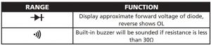
- Place the red test lead on the anode of diode and black test lead on the cathode of diode.
- The meter will show the approx. forward voltage of diode. Reverse voltage will indicate OL.
CONTINUITY CHECK
WARNING:
- To avoid electric shock, disconnect power to the unit under test and discharge all capacitors before taking continuity check
- Set the function switch to position and press the SEL button to choose continuity check mode
- Insert the black test lead banana plug into COM jack, insert the red test lead banana plug into INPUT jack.
- Touch the test probe tips across the circuit or component under test.
- If the resistance is <30Ω, the audible signal will be sounded.
TEMPERATURE MEASUREMENT
- Set the function switch to °C °F position, the value of environmental temperature shows in display. Press SEL button to shift °C mode or °F mode.
- Insert the red terminal of temperature probe into the INPUT jack, black terminal into COM jack, place the temperature probe tip where needed to measure.
- Read the temperature on the display
RESISTANCE MEASUREMENT
WARNING:
Due to external interference source, this function may cause wrong voltage detection, the detection result is for reference only.
Set the function switch to NCV position, contact the top part of meter with the circuit under test, the indicating LED will be flashed and audible signal will be sounded once detecting the voltage, the signal strength showed in LCD display.
NOTE:
- The detection result is for reference, do not determine the voltage by NCV detection ONLY
- Detection may interfere by socket design, insulation thickness and other variable conditions
- The external interference sources, such as flashlight, motor, etc, may cause the wrong detection
LINE (LIVE WIRE RECOGNITION) TESTSet the rotary switch to LINE position, connect the black test lead to COM jack and red test lead to VΩ jack, hold the insulation part of black test lead and not put into circuit under measurement; contact the red test lead to live wire, the buzzer of meter will be activated and red LED will be flickered, when the red test lead connect the earth line, the buzzer does not sound and LED will not flicker.
NOTE: When the circuit is in serious leakage (approx. over 15V), the red test lead even contact earth line, the buzzer of meter will be sounded and LED will be flickered.
CAPACITANCE MEASUREMENT
WARNING:
- To avoid electric shock, disconnect power to the unit under test and discharge all capacitors before taking capacitance measurement.
- Set the rotary switch to position and press the SEL button to choose mode .
- Insert the black test lead banana plug into COM jack, insert the red test lead banana plug into INPUT jack.
- Touch the test probe tips across the capacitance under test.
- Read the capacitance value in the display.
MEASUREMENT SPECIFICATIONS
Accuracy: ±(%readings + digit), warranty period: 12 months)The following guide is based on an environmental temperature of 18-28°C and humidity <80%.
DC VOLTAGE
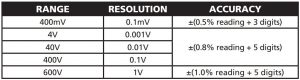
Input impedance: 10MΩ; Max. input voltage: 600V DC / 600V AC RMS
AC VOLTAGE
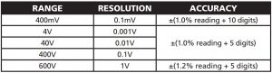
Input impedance: 10MΩ; Max. input voltage: 600V DC / 600V AC RMSFrequency response: TRMS40Hz-1kHz
DC CURRENT
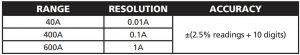
AC CURRENT
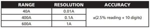
Frequency response: TRMS 40Hz-1kHz
RESISTANCE
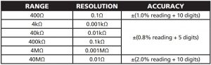
Overload protection: 250V DC or 250V AC RMS
DIYODE AND CONTINUITY
CAPACITANCE
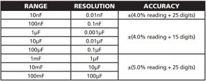
Overload protection: 250V DC or 250V AC RMSFREQUENCY
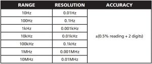
Overload protection: 250V DC or 250V AC RMS
TEMPERATURE
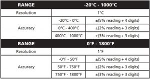
Overload protection: 250V DC or 250V AC RMS
MAINTENANCE
WARNING:
- To avoid electric shock, disconnect the test leads from any source of voltage before removing the back cover or the battery or fuse covers
- To avoid electric shock, do not operate the meter until the battery and fuse covers are in place and fastened securely
CLEANING AND STORAGEPeriodically wipe the case with a damp cloth and mild detergent, do not use abrasives or solvents. If the meter is not be used for a long time, remove the battery and shore it separately.
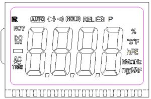
BATTERY INSTALLATIONTo avoid the false readings, replace the battery as soon as the battery indicator appears.
- Turn power off and disconnect the test leads from the meter.
- Open the rear battery cover by using screwdriver.
- Insert the battery into battery holder, observing the correct polarity.
- Put the battery cover back in place, secure with the screws.
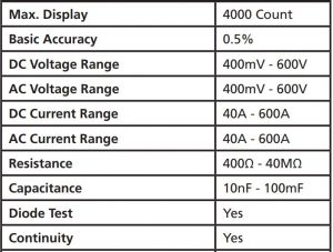
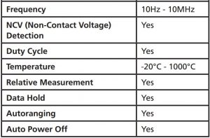
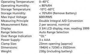
SPECIFICATIONS
BOX CONTENTS
- 1 x Clampmeter
- 1 x Test Leads
- 1 x Carry Case
- 1 x Temperature Probe
- 1 x User Manual
WARRANTY
This product is protected by a lifetime warranty (from the date of purchase) covering all product manufacturing defects/faults that may occur within this timeframe. This warranty does not cover damage caused by neglect, misuse, contamination, alteration, accident or abnormal conditions of operation or handling, including failures caused by use outside of the product’s specifications, or the normal wear and tear of mechanical components.
In the event that you suspect your product is defective/faulty, cease using the product when the suspected defect/fault arises and return the product along with proof of purchase to the place of purchase or distributor for assessment. Distributor contact details are available below.
If the assessment concludes that the product is indeed defective/faulty, the product will either be repaired or replaced at no cost to you.
Our goods come with guarantees that cannot be excluded under the Australian Consumer Law. You are entitled to a replacement or refund for a major failure and compensation for any other reasonably foreseeable loss or damage. You are also entitled to have the goods repaired or replaced if the goods fail to be of acceptable quality and the failure does not amount to a major failure.
Distributed by:TechBrands by Electus Distribution Pty. Ltd.320 Victoria Rd, RydalmereNSW 2116 Australia
Ph: 1300 738 555Int’l: +61 2 8832 3200Fax: 1300 738 500
References
[xyz-ips snippet=”download-snippet”]