DIGITUS DN-170107 Online Ups System 6 Kva / 10
Kva Installation Guide

Safety
Important safety instructions – Save these instructions
There exists dangerous voltage and high temperature inside the UPS. During the installation, operation and maintenance, please abide the local safety instructions and relative laws, otherwise it will result in personnel injury or equipment damage. Safety instructions in this manual act as a supplementary for the local safety instructions. Our company will not assume the liability that caused by disobeying local safety instructions.
Safety notes
- Even no connection with utility power, 208/220/230/240VAC voltage may still exist at UPS outlet!
- For the sake of human being safety, please well earth the UPS before starting it.
- Don’t open or damage battery, for the liquid spilled from the battery is strongly poisonous and do harmful to body!
- Please avoid short circuit between anode and cathode of battery, otherwise, it will cause spark or fire!
- Don’t disassemble the UPS cover, or there may be an electric shock!
- Check if there exists high voltage before touching the battery
- Working environment and storage way will affect the lifetime and reliability of the UPS. Avoid the UPS from working under following environment for long time• Area where the humidity and temperature is out of the specified range (temperature 0 to 40℃, relative humidity 5%-95%)• Direct sunlight or location nearby heat• Vibration Area with possibility to get the UPS crashed.• Area with erosive gas, flammable gas, excessive dust, etc.
- Keep ventilations in good conditions otherwise the components inside the UPS will be over-heated which may affect the life of the UPS.
Symbols used in this guide
![]() WARNING!
WARNING!
Risk of electric shock
![]()
CAUTION!
Read this information to avoid equipment damage.
Product Introduction
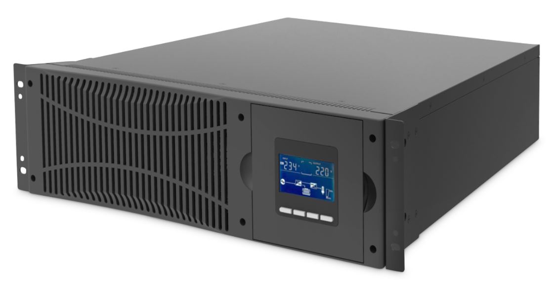
This series UPS is a kind of single phase in single phase out high frequency online UPS, it provides two capacities: The 6kVA and 10kVA. The products are modularized and adopt the N+X redundancy. It can flexibly increase the number of the UPS modules according to the load capacity which is convenient for flexible allocation and gradually investment.
Installation
Unpack checking
- Don’t lean the UPS when moving it out from the packaging
- Check the appearance to see if the UPS is damaged or not during the transportation, do not switch on the UPS if any damage found.Please contact the dealer right away.
- Check the accessories according to the packing list and contact the dealer in case of missing parts.
UPS Module Outlook
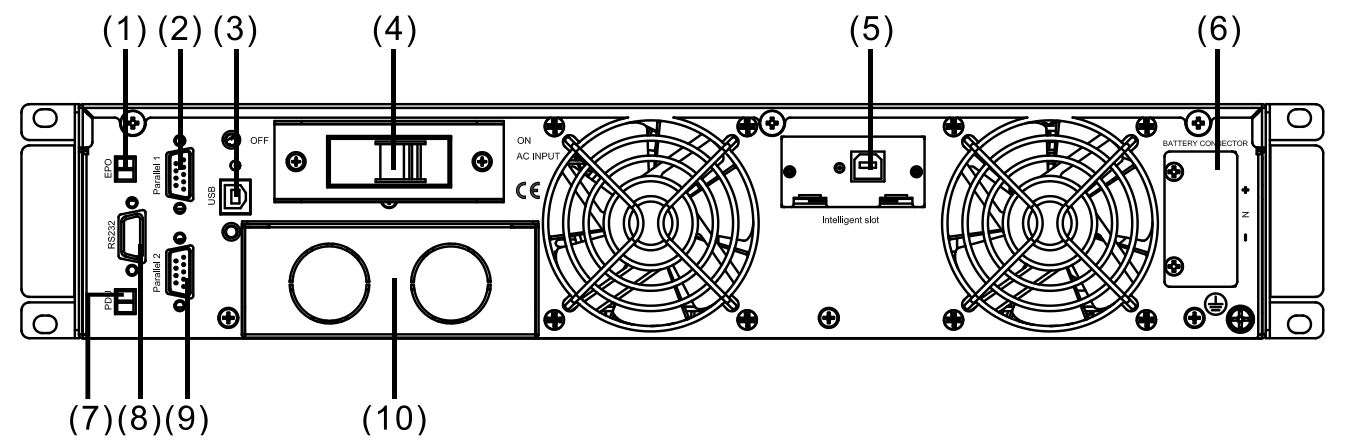
Rear View
- EPO
- Parallel Port 1
- USB
- Input breaker
- Intelligent slot
- Battery Slot
- PDU
- COM (RS232)
- Parallel Port 2
- Terminal
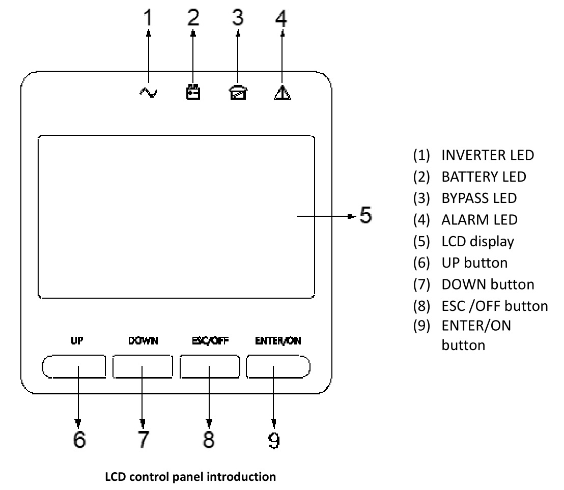
LCD control panel
Installation notes
- Please place the UPS in a clean, stable environment, avoid the vibration, dust, humidity, flammable gas and liquid, corrosive objects. To avoid from high room temperature, a system of room extractor fans is recommended to be installed. Optional air filters are available if the UPS operates in a dusty environment.
- The environment temperature around the UPS should keep in a range of 0°C ~40°C. If the environment temperature exceeds 40℃, the rated load capacity should be reduced by 12% per 5°C. The max temperature can’t be higher than 50°C.
- If the UPS is dismantled under low temperature, it might be in a condensing condition. The UPS can’t be installed unless the internal and external of the equipment is fully dry. Otherwise, there will be in danger of electric shock.
- Batteries should be mounted in an environment where the temperature is within the required specs. Temperature is a major factor in determining battery life and capacity. In a normal installation, the battery temperature is maintained between 15°C and 25°C. Keep batteries away from heat sources or main air ventilation area, etc.
![]() WARNING!Typical battery performance data are quoted for an operating temperature between 20°C and 25°C. Operating it above this range willreduce the battery life while operation below this range will reduce the battery capacity.
WARNING!Typical battery performance data are quoted for an operating temperature between 20°C and 25°C. Operating it above this range willreduce the battery life while operation below this range will reduce the battery capacity.
- Should the equipment not be installed immediately it must be stored in a room so as to protect it against excessive humidity and or heat sources.
![]() CAUTION!An unused battery must be recharged every 3months. Temporarily connecting the UPS to a suitable AC supply and activating it for the time required for recharging the batteries are required.
CAUTION!An unused battery must be recharged every 3months. Temporarily connecting the UPS to a suitable AC supply and activating it for the time required for recharging the batteries are required.
- The highest altitude that UPS may work normally with full load is 1500 meters. The load capacity should be reduced when this UPS is installed in place whose altitude is higher than 1500 meters, shown as the following table:
(Load coefficient equals max load in high altitude place divided by nominal power of the UPS)

To get the UPS completely monitored by the software, you just simply connect RS232 or USB cable to each end of the computer and the UPS respectively.
External Protective Devices
For safety reasons, it is necessary to install, external circuit breaker at the input A.C. supply and the battery. This chapter provides guidelines for qualified installers that must have the knowledge of local wiring practices for the equipment to be installed.
External Battery
The UPS and its associated batteries are protected against the effect of over-current through a DC compatible thermo-magnetic circuit-breaker (or a set of fuses) located close to the battery.
UPS Output
Any external distribution board used for load distribution shall be fitted with protective devices that may avoid the risk of UPS overloaded
Over-currentProtection device shall be installed at the distribution panel of the incoming main supply. It may identify the power cables current capacity as well as the overload capacity of the system.
![]() CAUTION!
CAUTION!
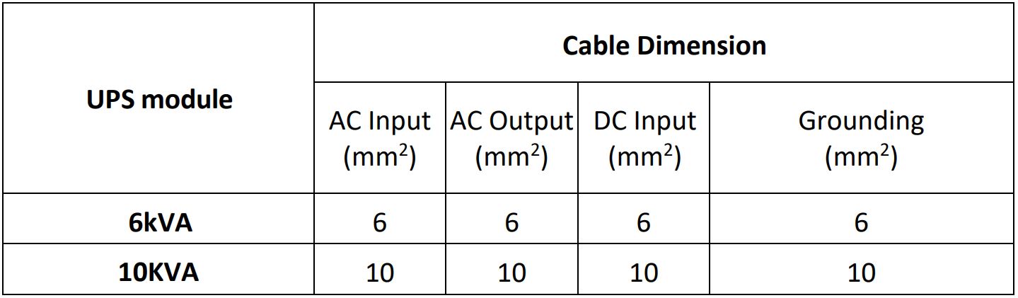
Select a thermo magnetic circuit-breaker with an IEC 60947-2 trip curve C (normal) for 125% of the current as listed below.
Power Cables
The cable design shall comply with the voltages and currents provided in this section, Kindly follow local wiring practices and take into consideration the environmental conditions (temperature and physical support media).
![]() WARNING!
WARNING!
Upon starting, please ensure that you are aware of the location and operation of the external isolators which are connected to the UPSinput/bypass supply of the mains distribution panel. Check to see if these supplies are electrically isolated, and post any necessary warning signs to prevent any inadvertent operation.
Cable Dimension
![]() CAUTION!Protective earth cable: Connect each cabinet to the main ground system. For Grounding connection, follow the shortest route possible.
CAUTION!Protective earth cable: Connect each cabinet to the main ground system. For Grounding connection, follow the shortest route possible.
![]() WARNING!
WARNING!
Failure to follow adequate earthing procedures may result in electromagnetic interference or in hazards involving electric shock and fire.
Power cable connect
Once the equipment has been finally positioned and secured, connect the power cables as described in the following procedure.Verify the UPS is totally isolated from its external power source and also all power isolators of the UPS are open. Check to see if they are electrically isolated, and post any necessary warning signs to prevent their inadvertent operation.Choose appropriate power cable, and pay attention to the diameter of the connection terminal of the cable that should be greater than or equal to that of the connection poles.
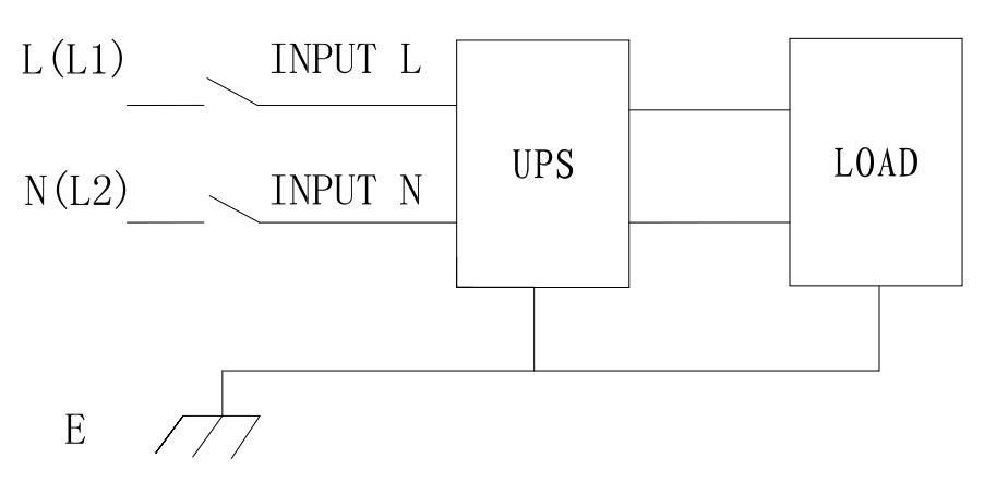
Input connection “single phase + ground”
![]() WARNING!If the load equipment is not ready to accept power on the arrival of the commissioning engineer then ensure that the system output cables are safely isolated at their ends.
WARNING!If the load equipment is not ready to accept power on the arrival of the commissioning engineer then ensure that the system output cables are safely isolated at their ends.
![]() CAUTION!
CAUTION!
The earthing and neutral bonding arrangement must be in accordance with local and national codes of practice.
Battery connection
The UPS uses a positive and negative double battery framework, total 16 (optional 18/20) pieces in series. A neutral cable is retrieved from the joint between the cathode of the 8th (9th/10th ) and the anode of the 9th (10th /11th) of the batteries. Then the neutral, the battery positive and the battery negative are connected with the UPS respectively. The battery sets between the Battery anode and the neutral are called positive batteries and that between neutral and cathode are called negative ones. Users can choose the capacity and the numbers of the batteries according to their demands. The connection is shown as following:

Note:
The BAT+ of the UPS connect poles is connected to the anode of the positive battery, the BAT- is connected to the cathode of the positive battery and the anode of the negative battery, the BAT- is connected to the cathode of the negative battery
Factory default setting for battery quantity is 16pcs and for battery capacity is 7AH (charger current 1A). When connecting 18pcs or 20pcs batteries, please re-set battery quantity and its capacity after UPS starts at AC mode. Charger current could be adjusted automatically according to battery capacity selected. (Also charger current is selectable). Via the setting tool, all related parameter settings can be performed. These corresponding settings are done though LCD.
![]() CAUTION!
CAUTION!
Ensure correct polarity battery string series connection. i.e. inter-tier and inter block connections are from (+) to (-)terminals. Don’t mix batteries with different capacity or different brands, or even mix up new and old batteries, either.
![]() WARNING!
WARNING!
Ensure correct polarity of string end connections to the Battery Circuit Breaker and from the Battery Circuit Breaker to the UPS terminals i.e. (+) to (+) / (-) to (-) but disconnect one or more battery cell links in each tier. Do not reconnect these links and do not close the battery circuit breaker unless authorized by the commissioning engineer.
Operation
Turn on/off UPS
Connecting with Utility
![]() CAUTION!
CAUTION!
Make sure grounding is properly done!
- Set the Battery Breaker to the “ON” position according to the user’s manual.
- Switch on the UPS
![]() WARNING!
WARNING!
Check to see if the load is safely connected with the output of the UPS. If the load is not ready to receive power from the UPS, make sure that it is safely isolated from the UPS output terminals
The internal fan of the UPS starts spinning, the UPS is performing selfdiagnostics until buzzer beeps twice to show the UPS is normal. Then, theUPS goes to bypass supply, Utility LED and Bypass LED turn Green, the inverter is starting up now. When the inverter is checked “normal”, the UPS goes to working mode and the load is supplied by the inverter now. No matter the UPS is operated normally or not, the LCD display will indicate current status. The top lines display the UPS operational status and the bottom lines indicate alarm conditions when they occur.
Disconnecting with Utility
![]() CAUTION!
CAUTION!
This procedure should be followed to completely shut down the UPS and the LOAD. After all power switches, isolators and circuit breakers are opened, there will be no output.
- After the inverter is off, turn the Utility and battery breakers to “OFF”, then the LCD display will extinguish completely and fan stops spinning in 60 seconds. If there are external battery packs connected, please also turn the battery breaker to “OFF”.
![]() WARNING!Wait for about 5 minutes for the internal D.C. bus bar capacitors to be completely discharged.
WARNING!Wait for about 5 minutes for the internal D.C. bus bar capacitors to be completely discharged.
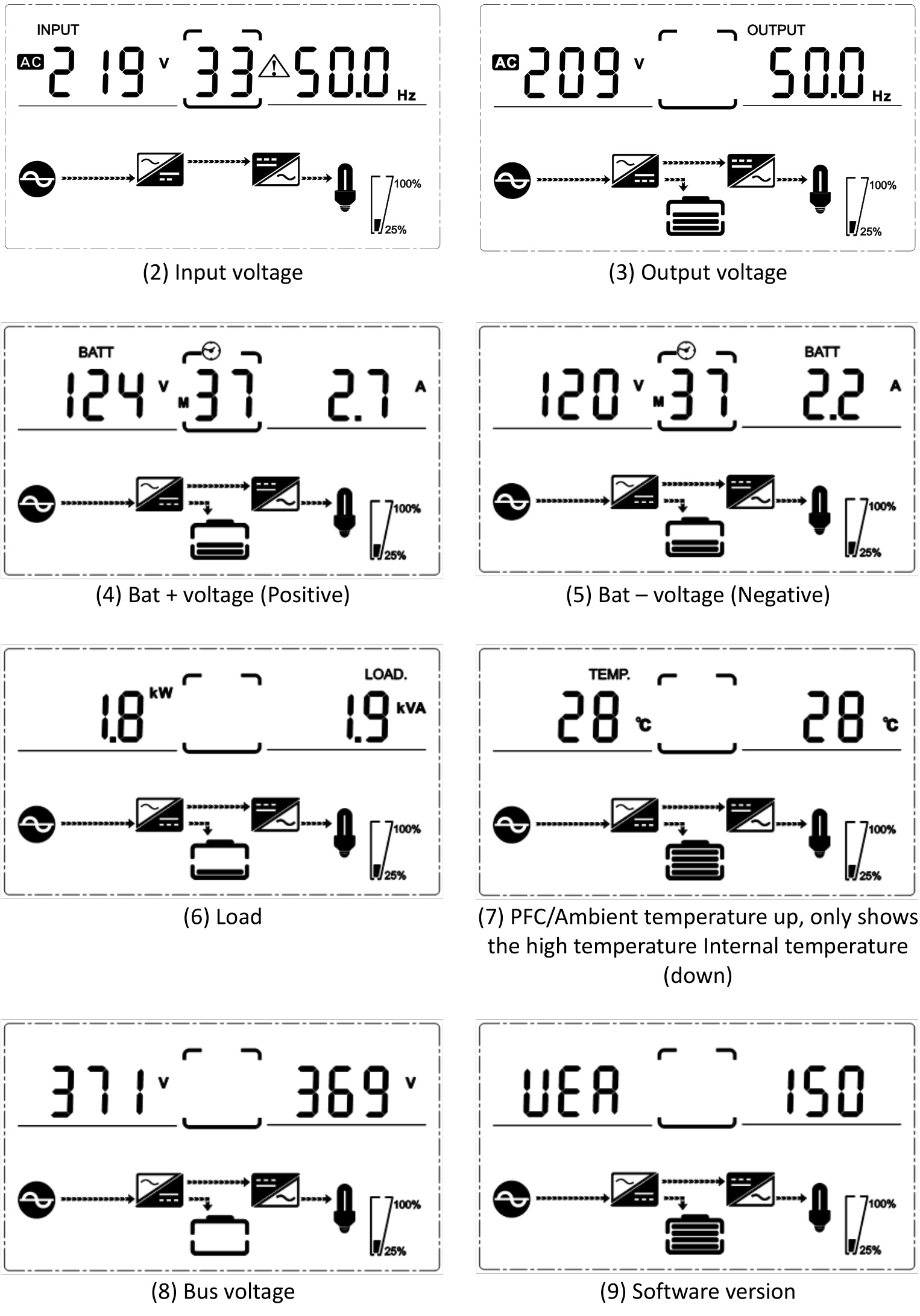
LCD Display instruction
NOTICE! The display provides more functions than those described in this manual. There are 10 interfaces available in the LCD display:

1. When the UPS is connecting with the Utility or Battery at cold start mode, it shows as drawing below:
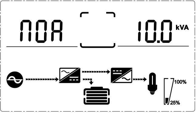
(1) Operational Status and mode
1) Operational Status and modeWhen the UPS at single mode, it shows “NOA” or “ECO” or “CF” or “GEN” or “SEF”, but If the UPS at parallel mode, it shows “PAL” instead2) Press “DOWN” button, the UPS goes to next page as shown below.
More detailed information on operation and device settings can be found in the corresponding user manual.
This is a Class A product. In home environment, this product may cause radio interference. In this case, the user may be required to take appropriate measures.Hereby Assmann Electronic GmbH, declares that the Declaration of Conformity is part of the shipping content. If the Declaration of Conformity is missing, you can request it by post under the below mentioned manufacturer address.
www.assmann.comAssmann Electronic GmbHAuf dem Schüffel 358513 LüdenscheidGermany
![]()
References
[xyz-ips snippet=”download-snippet”]