DIGITUS DN-95351 16-Port Gigabit Managed PoE Switch
Introduction
Gigabit managed switch designed and developed solely for the purpose of building high-performance gigabit network requirements. Provide a comprehensive security protection system Perfect QoS strategy and rich VLAN function Management and maintenance are simple and can be applied to small and medium enterprises Core layer of community and school.
Parameter
- Support Port/MAC/IP/VLAN ID four Yuan intelligent scanning binding
- Quickly locate user information, simplify operation and simplify network management.
- The CPU frequency of 500Mhz, 128M flash, 4M cache, 128M RAM.
- Support IEEE 802.1Q VLAN, Voice VLAN and other rich VLAN function.
- The comprehensive security system, tackling the problem, ensure long term stable operation of the network.
- The rich QoS strategy and control function of ACL multi service access, efficient integration of operation.
- Support multiple spanning tree protocol and port aggregation; improve the ability to link redundancy backup.
- Support STP, RSTP, MSTP fast spanning tree protocol; support EPPS, EAPS ring network protocol.
- The visual interface of POE, standard PO E duty management
- Support the CLI command line, Web network, SNMP SSH, a variety of management methods.
- The multiple timing restart function.
- We provide network diagnosis, cable detection, system log function.
Item list:Please open the switch package carefully, confirm the packing box should be as follows:
- 1*Managed Switch
- 1*power cable
- 1*User Manual
- 2*mounting brackets
- 4*mats
- 6*brackets screw
Product Display
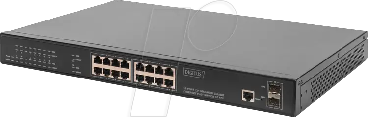
Front panel sketch map
- DN 95351: 16*10/100/1000M PoE Port+2*1000M SFP+1*Console, Rackmount, 19 inch steel case.
- DN 95352 : 24*10/100/1000M PoE Port+2*1000M SFP+1*Console, Rackmount, 19 inch steel case.
PWR:The indicator lights up to indicate that the switch is connected to the power supplySYS:CPU state indicator light, after the initialization is completed, per second flicker oncePoE:The indicator lights up, corresponding port is supplying power to the connecting deviceGiga/1000M:The transmission rate of the corresponding port is 1000MLink:Data transmission on the corresponding port.
Back panel sketch map
- The 19 inch steel case, back panel sketch map Power adapter interface: The power supply of the switch is inserted into the port, insert additional adapter Single phase three wire socket: The power supply of the switch is inserted into the port, and the input voltage of AC terminal is 100 240V 50/60Hz Grounding: Make the equipment ground.
Product mounting
AttentionIn order to avoid improper use of equipment damage and personal injury, please note the following:
- During the installation, the power supply remains closed, while wearing antistatic wrist, and ensure that antistatic wrist and skin good contact, to avoid potential safety hidden danger;
- The switch can work normally under the correct power supply. Please confirm that the supply voltage is consistent with the voltage indicated by the switch;
- Before the switch is switched on, please confirm that it will not cause over load of the power circuit, so as not to affect the normal operation of the switch or even cause unnecessary damage;
- In order to avoid the risk of electric shock, switch work should not open the shell, even in the case of no electricity, do not open on its own;
- Before cleaning the switch, the switch power plug should be pulled out, please do not wipe with wet fabric, please don’t use liquid cleaning;
- Install the equipment rack generally from the bottom, avoid overload installation;
- The switch surface to avoid placing other heavy objects, so as to avoid accidents.
Mounting Switch
Rack Mounting
- Check the grounding and stability of the rack.
- Secure the supplied rack mounting brackets to each side of the device with supplied screws, as illustrated in the following figure.
- After the brackets are attached to the device, use suitable screws (not provided) to secure the brackets to the rack, as illustrated in the following figure.

Desktop mounting
- To install the device on the desktop, please follow the steps:
- Set the device on a flat surface strong enough to support the entire bweight of the device with all fittings.
- Remove the adhesive backing papers from the rubber feet.
- Turnover the device and attach the supplied rubber feet to the recessed areas on the bottom at each corner of the device.
Connect PortConnect Ethernet portConnect an Ethernet port of the switch to the device by RJ45 cable as the following figure shows.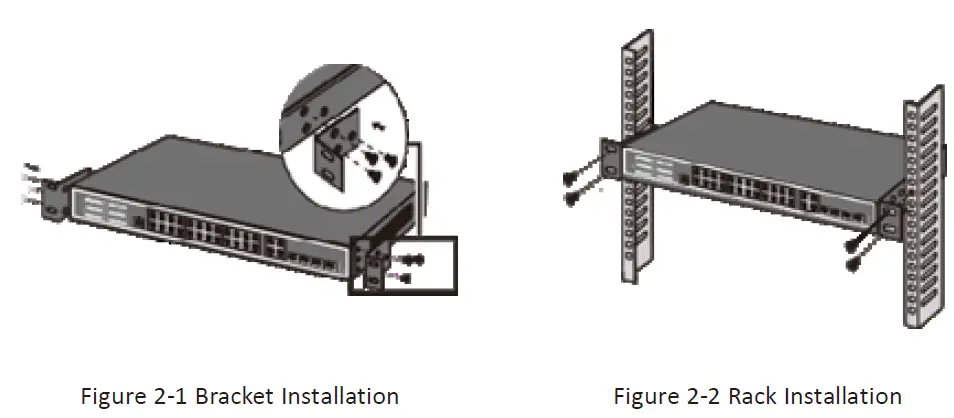
Connect SFP portThe optical fiber module is grabbed from the side and inserted smoothly along the switch SFP slot until the optical module is in close contact with the switchNote: to avoid improper operation cause damage to equipment or personal injury, please pay attention to the following matters.
- Excessive bending of optical fibers is not allowed, and the radius of curvature should not be less than 10cm.
- Ensure the cleanliness at the end of the fiber.
- Please do not look directly at the optical fiber connector; otherwise it may cause damage to your eyes.Remarks: it is recommended to adopt straight line 568B international standard connection method, as the following figure shows.
Power supply socket specificationSwitch power line single phase three wire power socket, the middle foot to ground, and the left foot on the right foot for the zero line and FireWire, please check before the operation.

Connect the power cordThe Rackmount direct access to AC100~240V, 50~60Hz city electricity.
Connecting to the Ground
The grounding cable is important to protect the switch from electrical interference. It is advised to use the grounding cable; if your power is ungrounded which could damage the switch or its functionality.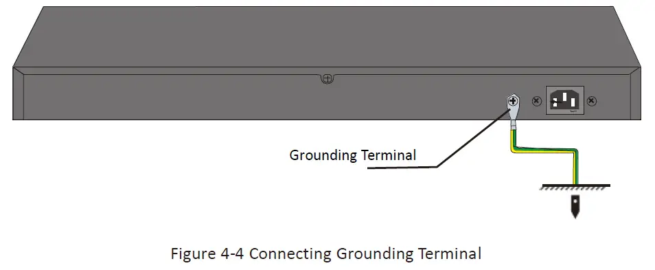
Note: The grounding bar and the ground cable are not provided with our product. If needed, please self purchase them.
Check after installationPlease check the following items after installation:
- check whether there is enough space for heat exchange, air circulation is smooth
- check the power supply socket power supply switch is in accordance with the specifications
- check the power supply, switchboard, rack and other equipment have been properly grounded.
Login the DeviceThe machine default IP address is 192.168.2.11, subnet mask is 255.255.255.0. So when you log on to the switch, make sure the IP address of the computer network card and the IP of the switch in the same network segment: 192.168.2. *** (1 <*** <25 5, *** is not equal to 11). Please enter user name: guest , password: guest then you can use the web browser based configuration to manage switch.
Managed PoE Switch Hardware Parameters
| Type | DN-95351 | DN-95352 |
|
Port |
16*10/100/1000M | 24*10/100/1000M |
| 2*SFP | 2*SFP | |
| 1*Console | 1*Console | |
| PoE standards | IEEE802.3af/at, single port PoE power 30W | |
| PoE Port | 16 | 24 |
| PoE Budget | 380W | |
| Reset | 1 | |
| Bandwidth | 56Gbps | 56Gbps |
| Packet forwarding | 40.32Mpps | 40.32 Mpps |
| CPU | 500Mhz | |
| RAM | 128M | |
| MAC | 8K | |
| Buffer | 4.1M | |
| FLASH | 128M | |
| Transmission | Store and forward | |
| Working
temperature |
0°C~50°C |
|
| Storage temperature | -40°C ~70°C | |
| Operating humidity | 10%~90% Non-coagulation | |
| Storage humidity | 5%~95% Non-coagulation | |
| Product size | 440*290*45mm | |
| Packing size | 497*313*97mm | |
| Power in | AC 100-240V, 50/60Hz | |
| Power Supply | 400W |
Management switch WEB software function
|
Standards |
IEEE 802.3x
IEEE 802.3, IEEE 802.3u, IEEE 802.3ab, IEEE 802.3z IEEE 802.3ad IEEE 802.3q, IEEE 802.3q/p IEEE 802.1w, IEEE 802.1d, IEEE 802.1S, IEEE802.1X |
| MAC Address | 16K MAC addresses; MAC address learning and aging |
|
VLAN |
STP (Spanning Tree Protocol) Up to 4095 VLAN
Voice VLAN, can configure QoS for voice data 4k VLANS; Port-based VLANs;802.1Q VLAN |
|
Spanning Tree |
STP (Spanning Tree Protocol)
RSTP/MSTP (Rapid Spanning Tree Protocol) EPPS ring network protocol 802.1x argumentation agreement |
| Link Aggregation | Max 8 aggregation groups TRUNK, each supports
8 ports Static aggregation and dynamic aggregation |
| Port Mirror | Many-to-one port mirroring |
|
Loop Guard |
Loop protection function, real-time detection, rapid alarm, accurate positioning, intelligent blocking, automatic recovery |
| Isolation | Support downlink ports isolated from each other and communicate with upstream port |
| Port flow control | Half duplex based back pressure control Full duplex based on PAUSE frames |
| Line rate | Support port-based input / output bandwidth management |
| IP binding | Support static ARP |
| Static routing | Support static routing |
|
IGMP Snooping |
Support 256 layers of set table capacity IGMPv1/2/3 and MLDv1/2 Snooping GMRP protocol registration Multicast address management, multicast VLAN, multicast routing ports, static multicast addresses |
| DHCP | DHCP Snooping |
|
Storm suppression |
Unknown unicast, multicast, unknown multicast, storm suppression of broadcast type Storm suppression based on bandwidth tuning and storm filtering |
|
Security |
Support 256 groups of ACL
Teams that support 4 different priorities per port User port + IP address + MAC ACL based on IP and MAC Security properties of port-based MAC address quantities Support system CPU self-protection |
|
QOS |
802.1p port queue priority algorithm
Teams that support 4 different priorities per port Cos/Tos, QOS sign WRR (Weighted Round Robin), Weighted priority rotation algorithm WRR, SP, WFQ, 3 priority scheduling models Support based on port, MAC, 802.1Q, DSCP classification |
| Port | Auto-MDIX; Auto-negotiation |
|
System maintenance |
Upgrade package upload system log view Support to upload / download configuration files through WEB Support multiuser management
WEB restore factory configuration |
|
PoE Management |
Open or close port
Standard POE scheduling management Power and current display Automatic restarting function of equipment dead machine Timing reactivation Support IP bindings restarting |
|
Management & maintenance |
WEB NMS
CLI Telnet, TFTIP Console, management based on Remote configuration and maintenance using Telnet SNMP V1/V2/V3; SSH V1/V2; RMON V1/V1 |
Hereby Assmann Electronic GmbH, declares that the Declaration of Conformity is part of the shipping content. If the Declaration of Conformity is missing, you can request it by post under the below mentioned manufacturer address.
 report this ad
www.assmann.comAssmann Electronic GmbHAuf dem Schüffel 358513 LüdenscheidGermany
References
[xyz-ips snippet=”download-snippet”]