
![]()
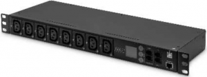
Smart PDU, 8 x C13,LCD info panel, WebUI,RJ45, RJ11, Sensor option
Manual
DN-95610
Safety and Grounding:
Read the following information before installing or operating your DIGITUS Power Distribution Unit:
- This PDU is intended for indoor use only.
- This PDU must not be operated one behind the other!
- Operation only in dry and closed rooms.
- This PDU may not be operated covered. Always ensure free accessibility.
- The maximum power stated on the rating plate must not be exceeded.
- Plug this PDU into a three-wire, grounded power outlet only. The power outlet must be connected to appropriate branch circuit/ mains protection (fuse or circuit breaker). Connection to any other type of power outlet may result in a shock hazard.
- Use only the supplied brackets of mounting.
- Check that the power cord, plug, and socket are in good condition.
- Voltage free only when the power plug is unplugged.
- Disconnect the PUD from the power outlet before you install or connect equipment to reduce the risk of electric shock when you cannot verify grounding. Reconnect the PDU to the power outlet only after you make all connections.
- Operation under unfavorable environmental conditions must be avoided. (Humidity over 80% relative, wet, ambient temperatures above 50 °C, solvents, flammable gases, dust, vapors).
- If external damage to this PDU is detected, do not operate this PDU. Take this PDU immediately out of service if external damage is detected.
- Do not pour liquids over the power strip. There is a high risk of fire or life-threatening electric shock.
- When opening the power strip, live parts can be exposed. There is a risk of electric shock. The power strip may only be opened by a specialist. When opening the power strip, live parts can be exposed. There is a risk of electric shock. The power strip may only be opened by a specialist.
I. Basic Introduction:
Digitus Smart Power Distribution Unit is the world-advanced new generation network power distribution and monitoring device. Through Network port, the manager can monitor, control and manage the power of many equipment in the cabinet of the data room located all over the world.
II. Package Content
Open the shipping carton and carefully unpack its contents. Please consult the packing list located in the User Manual to make sure all items are present and undamaged. If any item is missing or damaged, please contact the local reseller for replacement.
- Smart PDU 1pcs
- AC power cord 1pcs
- User’s manual 1pcs
- Mounting Accessory Pack 1pcs
- CD 1pcs
III. Smart PDU General Function Introduction
Smart PDU have the function of remote monitoring and remote controlling.It can implement total circuit and branch circuit monitoring and controlling.Remote monitoring function includes: total current, voltage, branch current, total power, total electric energy, temperature, humidity, smog, and water logging.Remote controlling function includes: total circuit switch control, branch circuit switch control, branch circuit time delay switch control, branch circuit timing switch control etc.System alarm function includes: local buzzer alarm and remote email alarm.
Product appearance
![]()
Smart PDU Function List
| Main function | Details |
Function |
| Monitor | Total current |
• |
| Outlet load current |
• |
|
| On/Off state of each outlet |
• |
|
| Total power(kw) |
• |
|
| Total energy consumption(kwh) |
• |
|
| Input voltage |
• |
|
| Frequency |
• |
|
| Temperature/Humidity |
• |
|
|
Smoke |
• |
|
| Water logging |
• |
|
| Control | Switch on/off individual outlet |
• |
| Delay switch on/off individual outlet |
• |
|
| Timing switch on/off individual outlet |
• |
|
| Configure | Set the delay of outlet sequential switching |
• |
| Clear the total energy consumption(kwh) |
• |
|
| Alarm | Total current upper limit |
• |
| Outlet current upper limit |
• |
|
| Temperature/Humidity upper limit |
• |
|
| Smoke |
• |
|
| Water |
• |
|
| Alarm method | Buzzer |
• |
|
• |
1.1 Overview
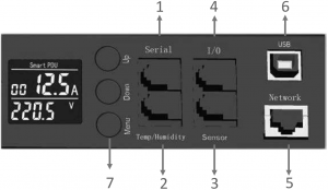
The Smart PDU has Ethernet port, RJ11 ports for RS485 interface, Temp/Humidity sensor, water & Smog Senor, and I/O interface etc.The interface definition is as blow:
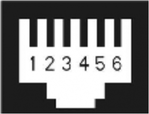
Input/output Interface instruction: 4 RJ11 ports, the order of corresponding pins are as below:
1.1.1 Serial
RS485 Serial communication port is used for local monitoring mainly and can be communicated with RS485 port locally. And also can be matched with HMI (Human Machine Interface) provided by the company. The communication Baud rate is 9600.
|
1 |
2 | 3 | 4 | 5 | 6 |
| GND | 485A- | 485A- | 485A+ | 485A+ |
GND |
1.1.2 Temp/Humidity
It is temperature and humidity interface. The temperature and humidity (IIC bus type sensor) is optional.
|
1 |
2 | 3 | 4 | 5 | 6 |
| GND | GND | SCL | SDA | +5V |
+5V |
The pins are as follows:
- SCL: Clock;
- SDA: data;
- GND: Grounding;
- +5V: Power Positive Pole
1.1.3 Sensor
It is universal transducer Interface and can be used for the sensor signal input such as smog, water logging switch. The smog and water sensors are optional.
|
1 |
2 | 3 | 4 | 5 | 6 |
| +24V | +24V | Water | SMOG | GND |
GND |
The pins are as follows:
- Water: water logging monitor.
- It is high potential at normal conditions. When it monitored low potential, it will be watering alarm.
- SMOG: Smog monitor. It is high potential at normal conditions.When it monitored low potential, it will be SMOG alarm.
- +24V and GND is power supply.
1.1.4 I/O
It is common digital value input/output. There are two routes for each input and output and can be used for status indicator of entrance (door) guard and output control of dry contact etc.
|
1 |
2 | 3 | 4 | 5 | 6 |
| GND | DI.0 | DI.1/DO.0 | DI.2 | DI.3/DO.1 |
+24V |
- D1.0-D1.3 is digital value electrical level input. The input level is between 7~24Vdc. These Pins can monitor input signal. When input level is higher than 7VDC, it can be regarded high level 1.Otherwise, it can be Low level 0.
- DO.0, DO.1 can be used for output control. It can be short to GND and used for entrance guard condition monitoring by default. The maximum drive capability should not exceed 200mA, 100Vdc.
If the entrance guard is passive switch signal, it can be used by connecting the 24V power simultaneously.Note: Currently door sensor is not available.
1.1.5 Network
It is network interface and used for TCP/IP internet network connections.
1.1.6 USB
It is common interface for USB port transforms to RS232 port, used as factory debugging console port.
1.1.7 Key
Function keys instructions
- UP: Page Up to view each loop current respectively, MODBUS protocol device ID, communication baud rate, IP address. Default data: ID=48; BAUD=9600, IP=192.168.2.55.
- DOWN: Page Down to view each loop current, IP address, baud rate, device ID, etc.
- MENU: Parameter Settings button, detailed setting method is as follows:
- Keep pressing “menu” button more than 3 seconds, after hearing the “drop” sound into the set state
- Press up and down keys, respectively, to view all below parameters.Id: Device numberBd: Baud rateUI: Upper limit of class I current; 12A: Upper limit of class II currentP11: Upper limit of level I branch current; P12: Upper limit of level II branch currentUU: Upper limit of voltage, UL: lower limit of voltageUT: Upper limit of temperature, LT: lower limit of temperatureUH: Upper limit of humidityED1: four DI/DO alarm enabled, LD1: four I/O normal settingEST: Smoke, Water alarm enabled, LST: Smoke, Water status settings
- ED1 and EST defaults to zero, when need to enable this feature, please set to 1.
- LD1 and LST defaults to zero, it indicates that the low level is normal, and high level is anomaly.If one is set to 1, it changes the high level is normal and low level of anomaly. Users have to set up correctly according to the actual use.
- In the current parameter display page, press “menu” button to enter a state of parameter modification. When the numbers start flashing, press the up and down key to modify the value. Press “menu” button again to confirm.
- Keep pressing the “menu” button for 5 seconds to exit the set state.• MENU+UP: Keep pressing the two buttons at the same time by more than 15 seconds, the equipment is reset to the factory settings and network module is restarted.
1.2 Introduction of software operation interface
1.2.1 Login interface
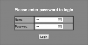
Default login parameters:IP Address: 192.168.2.55Name : 123Password : 123
Remarks: Whenever forget the IP address or password, you can press the MENU+UP buttons at the same time by more than 15 seconds, the system will reset to the default IP address: 192.168.2.55, and the default name: 123, default password : 123.
Note: This web user interface only allows one concurrent user to login.
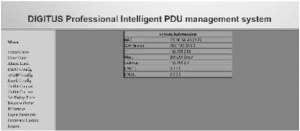
1.2.2 System Information Overview
From this interface, the MAC address, S/W Version, IP address, Subnet Mask, Gateway, Domain Name System IP address etc. can be checked.
1.2.3 Parameter Overview Interface
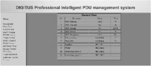
From this interface, the voltage, total current, electric energy, power, frequency, temperature humidity etc. can be checked.
1.2.4 Alarm value setting interface
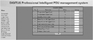
From this interface, the temperature upper limit, temperature lower limit, humidity upper limit, total current upper limit I, total current upper limit II, sublet current upper limit I, sublet current upper limit II, voltage upper limit, and voltage lower limit etc. can be set.
The temperature and humidity alarm is functioned with optional sensor installed.
1.2.5 DIDO value setting interface

From this interface, it is on-off setting for the switch type signal detection devices, including smoke, water and door sensors.
- No 1, 3, 5 and 7: alarm enable “1”, and alarm disable “0”.
- No 2, 4, 6 and 8: sensor alarm lever type. If sensor is closed output type (high potential), the value is 1. If sensor is open output type (low potential), the value is 0.
For example, normally smog sensor is closed output (high potential) type device.To enable alarm, alarm EN is 1, and lever type is 1.Normally, water sensor is open output (low potential) type device. To enable alarm, alarm EN is 1, and lever type is 0.
1.2.6 SNMP configuration setting interface
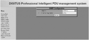
Users can Enable or Disable trap alarm from this interface.IP of the Trap Server: Fill in the trap address of SNMP management platform.Trap alarm information will be sent directly to the addresses.
1.2.7 Email alarm configuration setting interface
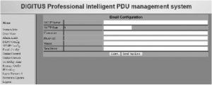
Fill in below parameters of Email alarm configuration.
- SMTP server: DNS of email server or IP address
- SMTP Port: 25
- Username: SMTP account
- Password: Password as SMTP email service enabled
- Mail to: the email address of receiver
After submitting the setting, it can be tested by send test email. Fill in the test string.It allows maximum 40 characters.
1.2.8 Remote device control interface

All the outlets or some individual outlets can be selected. The control action include “on immediate”, “on delay”, “off immediate”, “off delay” 4 types. “Delay on/off” action is only available after setting the delay time parameter.
1.2.9 Port Current Overview
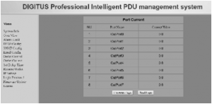
From this interface, the current of each outlet port can be checked.
1.2.10 Time delay parameter configuration interface
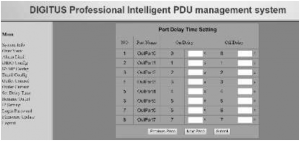
Please fill in the time delay on/off value for each outlet from this interface. The time unit is second and the max value is 999 seconds.
1.2.11 Rename Outlet interface
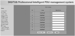
From this interface, you can rename outlet. Total length is not more than 20 characters.
1.2.12 Revise the IP address
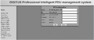
You have to fill in all the information for system IP, system mask, system gateway, and domain name system. When finished it, reboot smart PDU. The new IP address can be used.
1.2.13 Setting for login user name and password
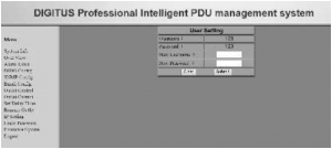
Setting and amending login user name and password can be done on this interface.
1.2.14 Firmware upgrade Interface
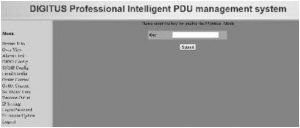
Firmware upgrade should be performed or supervised by technical and authorized personnel only.Authorized key is needed. Please contact your local dealer or reseller for service.
1.3 Technical parameters of the device
- Working voltage: single phrase 100~250VAC
- Working power current: 10A
- Working frequency: 50/60Hz
This is a Class A product. In home environment, this product may cause radio interference.In this case, the user may be required to take appropriate measures.
Hereby Assmann Electronic GmbH, declares that the Declaration of Conformity is part of the shipping content.If the Declaration of Conformity is missing, you can request it by post under the below mentioned manufacturer address.

www.assmann.comAssmann Electronic GmbHAuf dem Schuffel 358513 LudenscheidGermany
[xyz-ips snippet=”download-snippet”]