Smart Power Distribution Unit
QIGDN-95624/ DN-95625/ DN-95628/ DN-95629/ DN-95630/DN-95631/ DN-95632/ DN-95633/ DN-95634
Safety and Grounding:
Read the following information before installing or operating your DIGITUS PowerDistribution Unit:
- This PDU is intended for indoor use only.
- This PDU must not be must not be operated one behind the other!
- Operation only in dry and closed rooms.
- This POU may not be operated covered. Always ensure free accessibility.
- The maximum power stated on the rating plate must not be exceeded.
- Plug this PDU into a three-wire, grounded power outlet only. The power outlet must be connected to appropriate branch circuit/ mains protection (fuse or circuit breaker). Connection to any other type of power outlet may result in a shock hazard.
- Use only the supplied brackets of mounting.
- Check that the power cord, plug, and socket are in good condition.
- Voltage free only when the power plug is unplugged.
- Disconnect the PUD from the power outlet before you install or connect equipment to reduce the risk of electric shock when you cannot verify grounding. Reconnect the PDU to the power outlet only after you make all connections.
- Operation under unfavorable environmental conditions must be avoided. (Humidity over 80% relative, wet, ambient temperatures above 50 °C, solvents, flammable gases, dust, vapors).
- If external damage to this PDU is detected, do not operate this PDU. Take this PDU immediately out of service if external damage is detected.
- Do not pour liquids over the power strip. There is a high risk of fire or life-threatening electric shock.
- When opening the power strip, live parts can be exposed. There is a risk of electric shock. The power strip may only be opened by a specialist.
Smart PDU Introduction
The Smart Power Distribution Unit is a network manageable device that provides power monitoring, controlling, and management to many types of equipment in the rack cabinet of the data center through LAN or WAN. For meeting with the restrictions and requirements in a different environment, SMART PDU supplies many connection methods that user can manage it through its Web interface (HTTP or HTTPS), Serial connection, Telnet or SNMP.
- Product picture and description1. Vertical SMART PDU (OU)
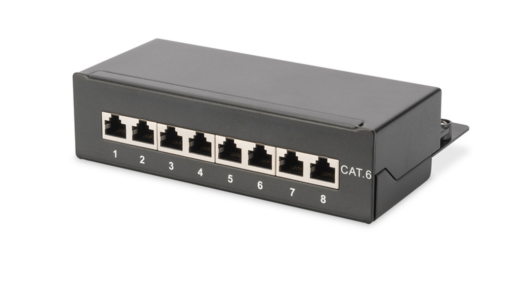
1. Input power cord;2. Brackets;3. Hydraulic circuit breaker;4. LCD screen;5. DOWN key: scroll down to the next page;6. UP key: scroll up to the previous page;7. ENTER: OK button;8. RUN indicator9. 1600imp/kWh Energy pulse indicator;10, RESET button;11. USB port for WIFI access or software upgrade;12. NET: 10/100M Ethernet communication port13. SER: Serial communication port (support MODBUS);14. IN: for daisy-chain15. OUT: for daisy-chain16. T/H1: temperature and humidity sensor port 117. T/H1: temperature and humidity sensor port 218. SENSOR: extend sensor hub communication port, sensor hub support 2 temperature/humidity sensor, 2 door sensor, 1 water logging sensor, and 1 smoke sensor19. LED indicator;20. Outlets
- InstallationVertical-mounting (OU)
- Function DescriptionThere are four series for the Smart PDU range. A, B, C, D series function comparison table:
A series B series C series D series Input-level Metering (A/V/VA/kWh/Power factor) Yes Yes Yes Yes Individual Outlet Metering No Yes No Yes Individual Outlet Switching No No Yes Yes A series: DN-95624/ DN-95625B series: DN-95628/ DN-95629C series: DN-95630/ DN-95631D series: DN-95632/ DN-95633/ DN-95634
Hardware Introduction
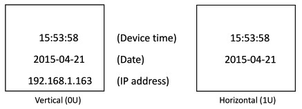
- System initializationThe buzzer sounds when the SMART POU is switched on and it stops after 3 seconds. Then the LCD screen is lighted after 6 seconds with the following information displayed:
 Note: 192.168.1.163 is the default IP address; and this is the first page after system initialization.
 - View System information1. View system informationPress ENTER to go to the main menuThrough the DOWN or UP key to scroll down or up to the next/previous page, turn to the main menu and select the first item Information, then press ENTER to go to the Information menu and the displayed information is as below:Note: the displayed information may differ from the device part number.CPU: ARM926EJ-S means the type of the device CPU chip; Version: 1.0.0 is the software version number; M/S: Master means the Master Unit and Slave 1 means the Slave unit 1(1-4 means the order of Slave unit); Type: 3 phase C means the device is 3 phase C series one. Through the DOWN or UP key to scroll down or up to the next/previous page, turn to the main menu and select the second item Total, then press ENTER to go to the Total menu and the displayed information are as below:Note: the above information is from a single-phase device, if it is a 3 phase one, the power date of each phase will be displayed as well. U: 214V means the input voltage, 1:00.0A means the total input current, P:0.000KW means the total power, E:000013.1kWh means the total power consumption, PF:0.00 means the power factor. Press ENTER to return to the main menu, and then press DOWN key to select Temp/Hum to view the temperature/humidity as below:Press ENTER to return to the main menu, and then press DOWN key to select Sensors to view the door, waterlogging, and smoke sensor status as below:Press ENTER to return to the main menu, then press DOWN key to select Group to view each group outlet current as below:Press DOWN or UP key to view the current of rest outputs:Note: Press UP button to view the previous page of device information.Press ENTER to return to the main menu, then press DOWN key to select Group to view each group outlet current as below.
 Note: 192.168.1.163 is the default IP address; and this is the first page after system initialization.
 Through the DOWN or UP key to scroll down or up to the next/previous page, turn to the main menu and select the first item Information, then press ENTER to go to the Information menu and the displayed information is as below:
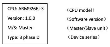 Note: the displayed information may differ from the device part number.CPU: ARM926EJ-S means the type of the device CPU chip; Version: 1.0.0 is the software version number; M/S: Master means the Master Unit and Slave 1 means the Slave unit 1(1-4 means the order of Slave unit); Type: 3 phase C means the device is 3 phase C series one. Through the DOWN or UP key to scroll down or up to the next/previous page, turn to the main menu and select the second item Total, then press ENTER to go to the Total menu and the displayed information are as below:
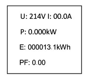 Note: the above information is from a single-phase device, if it is a 3 phase one, the power date of each phase will be displayed as well. U: 214V means the input voltage, 1:00.0A means the total input current, P:0.000KW means the total power, E:000013.1kWh means the total power consumption, PF:0.00 means the power factor. Press ENTER to return to the main menu, and then press DOWN key to select Temp/Hum to view the temperature/humidity as below:
 Press ENTER to return to the main menu, and then press DOWN key to select Sensors to view the door, waterlogging, and smoke sensor status as below:
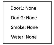 Press ENTER to return to the main menu, then press DOWN key to select Group to view each group outlet current as below:
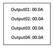 Press DOWN or UP key to view the current of rest outputs:Note: Press UP button to view the previous page of device information.Press ENTER to return to the main menu, then press DOWN key to select Group to view each group outlet current as below.
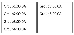
SMART PDU Software Introduction
- Software overviewSMART PDU is equipped with an embedded software system that provides a lot of network services like WEB server, SNMP, Telnet, SMTP, and NTP. It’s easy to do second development and software integration.
- Access methodWeb-based, can access via browsers like Internet Explorer, Google Chrome, and Firefox; supports WIFI (including the mobile device like smartphone and tablet), SNMP (v1 / v2c / v3), Telnet and Serial console-like MODBUS.1 Web accessOpen a browser and enter the default IP address, the login window will pop up like below, see figure-1.Fill in the correct user name and password (Factory default login name is admin, the password is admin) to login the main interface, see figure1-2
Mainly 3 parts on main interface: Navigation menu, Device information and Output status. Navigation menu: show company logo and function menus and a language selector.Device information: display device name, device series, and device status and function level. Output status: display output name, on/off state, individual current, individual power, power factor and environment status. From the drop-down menu of device to check the information of Slaves.More detailed information on operating and configuring the device can be found in the corresponding user manual.
 Fill in the correct user name and password (Factory default login name is admin, the password is admin) to login the main interface, see figure1-2
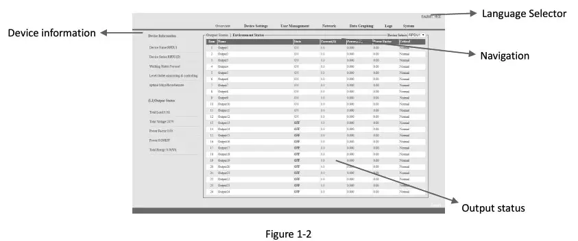
Technology Parameters
| No. | Performance parameter | Technical parameter | |
| 1 | Input | Rated input voltage | 110/220VAC 50/60 Hz; |
| Rated input plug | IEC60309 standard | ||
| Cable specification | 16A:3×2.5mm2 32A:3×6.0mm2; | ||
| Cable length | 2.5M | ||
| Max. load current | 16A, 32A | ||
| Overload protector | 1P circuit breaker | ||
| 2 | Output | Socket standard | Standard IEC320 C13, C19 |
| Socket quantity | A Series: DN-95624 (24way), DN-95625 (42way)B Series: ON-95628 (20way), DN-95629 (24way);C Series: DN-95630 (24way), DN-95631 (24way);D Series: DN-95632 (24way) DN-95633 (16way), DN-95634 (24way); | ||
| Output voltage | 110/220VAC 50/60 Hz | ||
| Output current | 16k 32A | ||
| 3 | Control ports | Net port | 1xR145 port |
| Daisy chain port | 2xR145 port | ||
| Software update port | 1×1:1145 port | ||
| Temperature & humidity port | Max 2xf111 port (can add more) | ||
| Smoke sensor port | Max lxR111 port (optional ) | ||
| Water sensor port | Max 1xR111 port ( optional ) | ||
| Door sensor port | Max 1xR111 port (optional ) | ||
| 4 | Display | Working state | 1xLED |
| Power pulse | 1xLED | ||
| IP Address, MIS SMART PDU state, measurement value, alarm state | LCD screen ( Resolution: 128×64) | ||
| 5 | Load current display technology | Total current | Full•scale:16/5.132A, Accuracy:±1%+0.2 Resolution:200mA, Response:400ms |
| requirement | Individual load current | Full-scale: 10A/ 16A, Accuracy:±1%+0.1, resolution:100mA, Response:400ms | |
| 6 | Temperature/humi dityTechnology requirement | Temperature | Accuracy:±1°C, Response: 400ms |
| Humidity | Accuracy:±5%RH, Response: 400ms | ||
| 7 | Product size | Product size (LxWxH ) | X2x56x52mm |
| Mounting hole | X3 | ||
| 8 | Case color | Color | Black |
| 9 | Fittings | Installation bracket | 1 set |
| Network connection cable | 2M blue network cablel | ||
| Daisy-chain connection cable | 2M yellow network cablel | ||
| Serial connection cable | 2M Ivory Serial cablel | ||
| User manual | 1 set (CD) | ||
| 10 | Optional fittings | Sensor | Temperature/humidity sensor |
| Smoke sensor | |||
| Door sensor | |||
| Waterlogging sensor | |||
| 11 | Environment | Working Environment | Temperature: Oct –+45°C Relative humidity: 30%—90% |
| Storage Environment | Temperature: -20°C–+70°C Relative humidity :0%-95% | ||
| 12 | ROHS | Compliance |
This is a Class A product. In-home environment, this product may cause radio interference.In this case, the user may be required to take appropriate measures.Hereby Assmann Electronic GmbH declares that the Declaration of Conformity is part of the shipping content.If the Declaration of Conformity is missing, you can request it by post under the below-mentioned manufacturer address.
www.assmann.comAssmann Electronic GmbHAuf dem Schiffel 358513 LidenscheidGermany
[xyz-ips snippet=”download-snippet”]