
DIGITUS DN-95639 19 Automatic Transfer Switch Installation Guide![]()
Safety and Grounding
Read the following information before installing or operating your DIGITUS Automatic Transfer Switch:
- This ATS is intended for indoor use only.
- This ATS must not be operated one behind the other!Operation only in dry and closed rooms.
- This ATS may not be operated covered. Always ensure free accessibility.
- The maximum power stated on the rating plate must not be exceeded.
- Plug this ATS into a three-wire, grounded power outlet only. The power outlet must be connected to appropriate branch circuit/ mains protection (fuse or circuit breaker). Connection to any other type of power outlet may result in a shock hazard.
- Use only the supplied brackets of mounting.
- Check that the power cord, plug, and socket are in good condition.
- Voltage free only when the power plug is unplugged.
- Disconnect the PUD from the power outlet before you install or connect equipment to reduce the risk of electric shock when you cannot verify grounding. Reconnect the ATS to the power outlet only after you make all connections.
- Operation under unfavorable environmental conditions must be avoided. (Humidity over 80% relative, wet, ambient temperatures above 50 ° C, solvents, flammable gases, dust, vapors).
- If external damage to this ATS is detected, do not operate this ATS. Take this ATS immediately out of service if external damage is detected.
- Do not pour liquids over the power strip. There is a high risk of fire or lifethreatening electric shock.
- When opening the power strip, live parts can be exposed. There is a risk of electric shock. The power strip may only be opened by a specialist.
Product Schematic
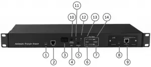
- Alarm: the port of buzz and flesh, used to connect to external annunciator
- RS232: Serial communication port, connect the device to local PC
- LED screen: display the current; voltage; IP address and hardware version
- Reset: Rest button
- Preference: to select the preferred power source
- Input indicator of source B
- Output indicator of source B
- RUN: Operation indicator
- NET: Ethernet Port
- Press to select data: To view power date and information
- Preference indicator of source A
- Preference indicator of source B
- Input indicator of source A
- Output indicator of source A
Accessories list
- One serial cable
- One network cable (only intelligent ATS)
- Four Ø 6 x 16 mm cross bolt
- One user manual and CD
- Optional accessories5.1. Circuit breaker (either circuit breaker or surge protection)5.2. Surge protection module (either surge protection or circuit breaker).
Mounting Method
Horizontal rack mounting
Hardware Introduction
- Self-checking when power onThe buzz beep once when power on, the LED indicator always lights on, digital screen display load current after self-checking.
- Operation status viewingThrough “press to select date” button, user can view the voltage; IP address (only intelligent type) and device version number.
- Select the preferred power source.Use Preferred button to select the primary power source, three options users can have: set the source A as the preferred power source; set the source B as the preferred power source; or user can leave this open. The corresponding indicator will always light on if a choice was made. If not, the two indicators will stay the off status. Please be noted that the intelligent ATS is with the Lock function, if user cannot do the setting above, please log on to the Web web interface to unlock.
- Reset operation.If want to manual-reset ATS, Press the Reset button to reset the rack PDU without affecting the outlet status.
- Restore to factory settingsPress and hold the “press to select data” button for 6 seconds, the LED screen will display “IP” when release, then press the Reset to restore to the default IP 192.168.1.163 and default Username and password.
- Serial connectionUse the supplied serial cable, insert the RJ45 connector to RS232 communication port and connect the other end to the serial port of local PC.
- External connection annunciatorUse the supplied terminal to connect the annunciator, the terminal allows maximum voltage of 50VDC and load current of 5A.
- Ethernet connection (only intelligent type)Use supplied network cable, connect one side to the NET port of device and the other end to network.
Software user guide
- Software configuration
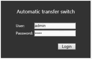
- Device default settingsDevice default IP: 192.168.1.163Default username: adminDefault password: adminNote: Both the default username and password are in lowercase, user cannot log on to the interface with uppercase.
- Device configuration when first log in
- Connect the device to PC directly.
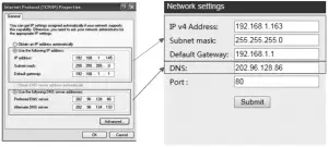
- Rework the network configuration of PC, make sure the changed PC IP address and the IP of the ATS is in the same segment, the default of the IP address is 192.168.1.163; Default subnet Mask is 255.255.255.0; Default gateway is 192.168.1.1. For instance, change the network configuration of the PC to IP: 192.168.1.145; log on to the management interface.
- Click the “Network Config” on the left menu to rework the IP of the ATS, see the below interface, change the IP address of the ATS and make sure it is in the same segment where the PC IP is.
- Restore the PC network configuration, Sign into the management interface with the changed IP address of ATS.

- Access methodConnect the device to LAN or WAN, user can access and manage the device through Web and SNMP, please see detail information as below. 2 WebDevice support HTTP protocol, we recommend user to access through IE 6.0, IE 7.0, IE 8.0, IE 9.0, Firefox and Google chrome, the Web access method are as below:
- Open the browser.
- Enter the IP address of the ATS in the address bar, support HTTP protocol (user can enable or disable the HTTP function according to situation, for more information please refer to Network Config menu)
- Enter the valid username and password in the login window.
- The below interface will show up if log success.More detailed information on operation and device configuration can be found in the corresponding user manual.
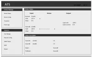 More detailed information on operation and device configuration can be found in the corresponding user manual.
Quality guarantee
The product is guaranteed for two years from the date of purchase. If product has already exceeded the warranty period or the problem are caused because of improper operation, a corresponding fee will be charged.
The below cases are not covered by the warranty:
- Problem caused because of improper maintenance.
- Problem caused because of unauthorized change, modify or improper use.
- The device are not used in the stipulate physical environment.
Hereby Assmann Electronic GmbH, declares that the Declaration of Conformity is part of the shipping content. If the Declaration of Conformity is missing, you can request it by post under the below mentioned manufacturer address.
Vist: www.assmann.comAssmann Electronic GmbHAuf dem Schüffel 358513 LüdenscheidGermany![]()
![]()

References
[xyz-ips snippet=”download-snippet”]