DIGITUS DN-98000 Basic Monitoring System, 4 x Relay Output, 12 x Signal Input Installation Guide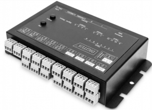
Dear Customer,
This quick start guide will enable you to start up your device. More detailed information on operating it can be found in the corresponding user manual. It is available at Digitus.info.
Security Advice
- The device must be installed only by qualified personnel according to the following installation and operating instructions.
- The manufacturer does not accept responsibility in case of improper use of the device and particularly any use of equipment that may cause personal injury or material damage. The device contains no user-maintainable parts. All maintenance has to be performed by factory trained service personnel.
- The device may only be connected via a low voltage power supply to 230V AC (50 Hz or 60 Hz) power supply sockets.
- The device is intended for indoor use only. Do NOT install them in an area where excessive moisture or heat is present.
- Because of safety and approval issues it is not allowed to modify the device without our permission.
- The device is NOT a toy. It has to be used or stored out of range of children.
- Care about packaging material. Plastics has to be stored out of range of children. Please recycle the packaging materials.
- In case of further questions, about installation, operation or usage of the device, which are not clear after reading the manual, please do not hesitate to ask our support team.
Installation
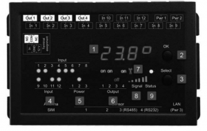
- Sensor Information (7-segment display
- OK Button
- Select Button
- 12 LED’s signaling the state of the Input
- LED display for power supply (1 = Pwr1, 2 = Pwr2,3 = Pwr3 (POE))
- 4 plain text displays (on/off) for the state of the Output Ports
- Status LED
The Status LED shows the different states of the device:
- red: The device is not connected to the Ethernet.
- orange: The device is connected to the Ethernet and waits for data from the DHCP
- server. green: The device is connected to the Ethernet and the TCP/IP settings are allocated.
- periodic blinking: The device is in Boot loader mode

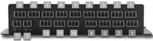
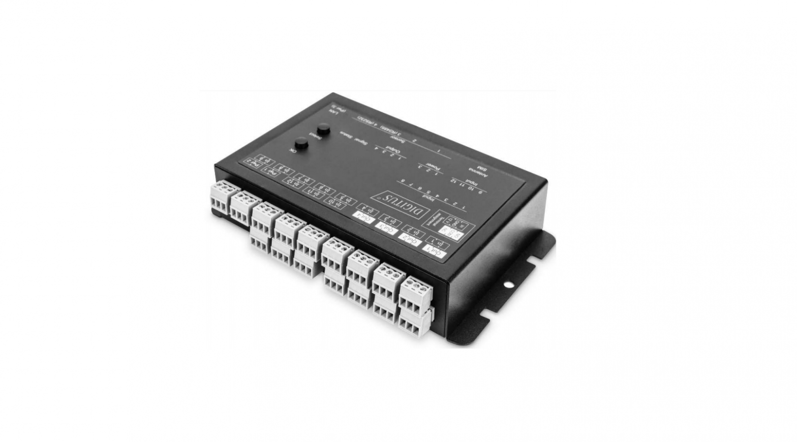
- 12 passive inputs (yellow)
- 4 potential-free relay outputs (red)
- 2 Connectors (Pwr1 + Pwr2) for power supply 12 V DC, 1 A (green)
- Connector Sensor Port 1
- Connector Sensor Port 2
- Connector Sensor Port 3 (RS485)
- Connector Sensor Port 4 (RS232)
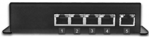
- Ethernet connector (RJ45)
Power Supply
If the device has PoE or a second input for the supply voltage, all voltage sources can be connected at the same time. This allows redundancy in the power supply.
Start-up the device
- Connect the device (Pwr1 or Pwr2) to the AC Adaptor (12 V DC, 1 A).
- Optional connect the device to a second AC Adaptor (12 V DC, 1 A).
- Plug the network cable into the Ethernet (RJ45).
- Attach the optional external sensors to the connectors
- Connect the passive inputs and relay outputs to compatible devices
Connect to the TCP/IP network
Connect your device to the network by plugging in the connector cable to the Ethernet connector. The device searches for a DHCP server and requests an available IP address. Check in the DHCP server settings, which IP address has been allocated. If necessary, make sure that the same IP address will be assigned at every re-start. The status LED shines shortly orange before it turns constantly green. Your device is now connected to the TCP/IP network and ready for operation.
Set-up and using features
The web interface is the central control panel of your device (see Fig. 1). You can access it from any PC in the same TCP/IP network.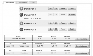
Fig. 1. Interface of Web interface
By accessing the web interface, you can
- configure all device settings and
- use all features of your device (e.g., switching power outlets or retrieving sensor values).
You can access the web interface of your device as follows:
- Open the web browser of a PC being in the same network.
- Enter the following into the address bar of your web browser:http://“device IP address”/(default: 192.168.0.2)
- Log in.In case that your device can not be found at the address entered, use our configuration program GBL_ Conf.By using GBL_ Conf you can
- configure all network and security settings and
- restore to default settings.
Set-up by using the configuration program
The most current version of GBL_Conf can be found at Digitus.info. Download and open the provided file and follow the onscreen instructions. After successful installation, please follow these steps:
- Open GBL_Conf. All found devices in the network will now appear in the left window as shown in Fig. 2.
- Double-click on the device name. You will be forwarded automatically to the device‘s web interface in your web browserFig. 2. AII found devices in the configurations program GBL_Conf.
 Fig. 2. AII found devices in the configurations program GBL_Conf.
This is a Class A product. In home environment, this product may cause radio interference. In this case, the user may be required to take appropriate measures.
Hereby Assmann Electronic GmbH declares that the Declaration of Conformity is part of the shipping content. If the Declaration of Conformity is missing, you can request it by post under the below mentioned manufacturer address.
www.assmann.comAssmann Electronic GmbHAuf dem Schüffel 358513 Lüdenscheid Germany


[xyz-ips snippet=”download-snippet”]