DIGITUS DS-12890 KVM Switch, 4-Port, 4K60Hz, 4 x DP in,
1 x DP/HDMI out Installation Guide

DEAR CUSTOMERThank you for purchasing this product. For optimum performance and safety, please read these instructions carefully before connecting, operating or using this product. Please keep this manual for future reference.
INTRODUCTION
This is a high-performance DP-KVM switcher. It routes high definition video (in multiple resolutions up to ) and audio from any one of the several sources to display units. This DP-KVM switcher not only has the key-press-switching function, but also has intelligent function as well as hot pluggable function.
PACKAGE CONTENTS
Before attempting to use this unit, please check the packaging and make sure the following items are contained in the shipping carton:
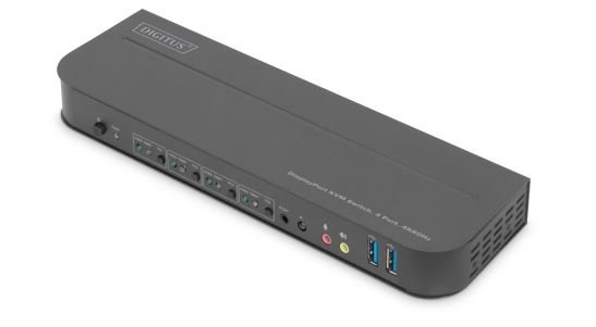
- 1 x KVM Switch, 4-Port, 4K60Hz, 4 x DP in, 1 x DP/HDMI out
- 1 x Power adapter for KVM switch
- 4 x USB 3.0 connection cable (USB B to USB A)
- 4 x DisplayPortTM cable 1.2 m
- 1 x Infrared remote control
- 1 x Infrared recipient with connection cable
- 2 x Mounting bracket for table/wall installation
- 1 x User manual
FEATURES
- Support resolution up to
- Support RGB 4:4:4/ YCbCr 4:4:4/ YCbCr 4:2:2/ YCbCr 4:2:0
- Support KVM function
- Support a display (Either DP or HDMI) and a set of Keyboard and Mouse to control four PCs with DP ports
- DisplayPort:Support 8.1Gbps per channel (32.4Gbps all channels) bandwidthSupport 16bit per channel (48bit all channels) deep colorSupport HDCP 2.2/1.4Support HDR
- Support infrared remote control function
- Support for switching LED indications
- Support Windows 2000/XP/Vista/Win7/Win8/Win10/Win11 and above /Linux/ Apple Mac O
PANEL DESCRIPTION
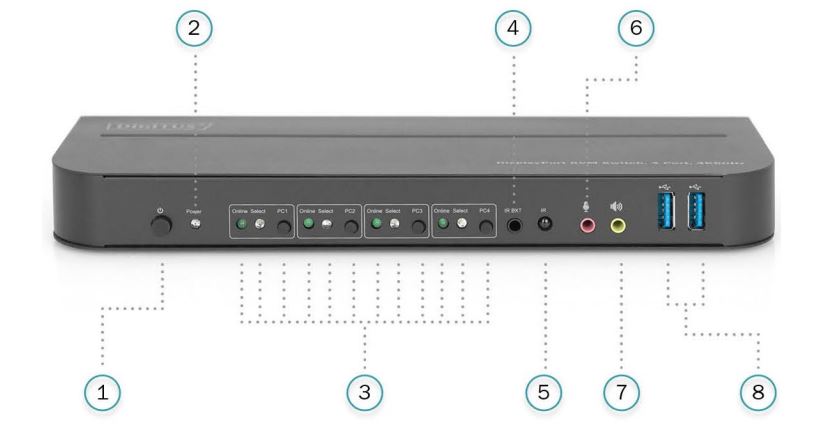
Front Pane
- Power Button: Press to turn on/off the unit.
- Power Indicator: The LED will light up once the DC/5V is provided and the unit is turned on.
- Input Selection: When PC1/PC2/PC3/PC4 is selected, the corresponding “Select” lights up to indicate input selection (“Select” LEDs flash in a loop under automatic switching mode). “Online” LED lights up when the corresponding USB-B port is connected.
- IR EXT: Connect IR Extender to this port for IR signal reception from the remote control.
- IR: For IR signal reception from the remote control.
 3.5mm MIC input port.
- 3.5mm stereo output port.
- USB 3.0 ports, mainly used for connecting to printers, scanners, U-disk, etc.
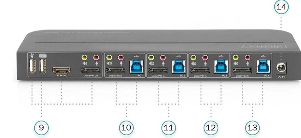
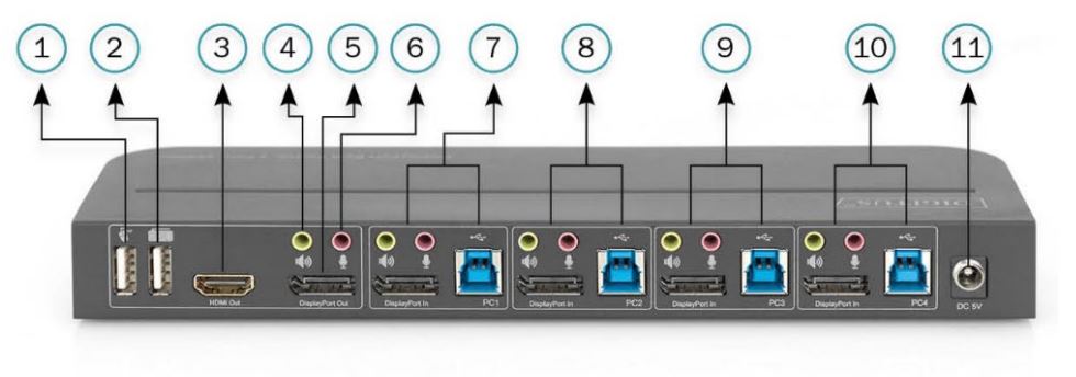
Back Panel
9. Output ports:Connect ![]() to a mouse or a keyboard.Connect
to a mouse or a keyboard.Connect ![]() to a keyboard or a mouse.Connect
to a keyboard or a mouse.Connect ![]() to an amplifier.Connect
to an amplifier.Connect ![]() to a MIC.Connect “HDMI Out” to HDMI display.Connect “DisplayPort Out” to DP display.10. PC1 input ports:Respectively connect to DisplayPort, USB, MIC, stereo ports of PC1.11. PC2 input ports:Respectively connect to DisplayPort, USB, MIC, stereo ports of PC2.12. PC3 input ports:Respectively connect to DisplayPort, USB, MIC, stereo ports of PC3.13. PC4 input ports:Respectively connect to DisplayPort, USB, MIC, stereo ports of PC4.14. DC 5V: Plug the 5V DC power supply into the unit.
to a MIC.Connect “HDMI Out” to HDMI display.Connect “DisplayPort Out” to DP display.10. PC1 input ports:Respectively connect to DisplayPort, USB, MIC, stereo ports of PC1.11. PC2 input ports:Respectively connect to DisplayPort, USB, MIC, stereo ports of PC2.12. PC3 input ports:Respectively connect to DisplayPort, USB, MIC, stereo ports of PC3.13. PC4 input ports:Respectively connect to DisplayPort, USB, MIC, stereo ports of PC4.14. DC 5V: Plug the 5V DC power supply into the unit.
SPECIFICATIONS

CONNECTION AND OPERATION
Operation
- Connect PCs to USB-B ports of the unit with USB cables; Respectively connect MIC and stereo ports of the PCs to those(above the “DisplayPort In”) of the unit with 3.5mm audio cables; Connect PCs to “DisplayPort In” ports of the unit with DisplayPort cables.
- Connect keyboard and mouse to the USB-A ports on the back panel of the unit; Respectively connect microphones and amplifiers to the mic and stereo ports(on the front panel/above “DisplayPort Out”) of the unit with 3.5mm audio cables; Connect a display to “DisplayPort Out” of the unit with a max 2m DisplayPort cable.(Or connect a display to “ HDMI Out” of the unit with an HDMI cable)Note: When either “DisplayPort Out” or “HDMI Out” is connected, video is output by the connected port automatically; When two of them are connected, video is output by DisplayPort.
- Power the unit with DC 5V and press the power button, the “Power” indicator lights up.The USB-B ports are connected normally and the “Online” indicators light up. “Select” lights up to indicate the current selected PC.
- Press the buttons on the front panel of the unit to select input, the corresponding “Select” lights up. After selection, the display showscorresponding image and the selected PC can be controlled by a set of keyboard and mouse.
- Remote control works the same as manual buttons.

1,2,3,4: For input selection. 1 specifies PC1, 2 specifies PC2, 3 specifies PC3 and 4 specifies PC4.
![]() ,
,![]() For loop switching. Order: PC1→PC2→PC3→PC4→PC1….
For loop switching. Order: PC1→PC2→PC3→PC4→PC1….
6. For external function, connect printer/scanner/U-disk to the USB-A ports on the front panel of the unit.
Special Function Operation:
- Mouse traversal function:Place the mouse on the far right side of the display and continue to slide to the right for 2 seconds, the unit automatically switches to the next port. Switching order is : PC1→PC2→PC3→PC4→PC1→…;
- USB-B detection switching function:• When the unit detects that a PC is connected to the USB-B port of the unit, the unit immediately switches to this PC and the corresponding “Online” and “Select” indicators light up. (For example: When PC1 is connected already, PC3 is connected to the unitthrough USB-B port, then the unit immediately switches to PC3.• When the current selected PC is powered off or the USB cable is dialed out, the unit automatically switches to the next PC with the power on and the USB port connected.
- Hotkey function(It doesn’t work on functional keyboard and only the 2 USB-A ports on the back panel can get access to this function.)
Note
- Hot keys are not case-sensitive;
- Buzzer sounds when switching between PC1 PC2, PC3 and PC4.
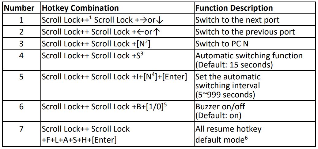
- “++” means to press 2 times in rapid succession. For example: “Scroll Lock ++ Scroll Lock + 1” means to press the Scroll Lock button twice in rapid succession and then press number “1” button. The detection between each hotkey code times out for 5 seconds. For example, if the Scroll Lock button is pressed for the first time, and then the Scroll Lock button is pressed after more than 5 seconds, the hotkey combination is invalid;
- “N” here indicates the number of the PC. For example, to switch to PC2, the hotkey combination is “Scroll Lock ++ Scroll Lock + 2”;
- Turn on this function, then DisplayPort, MIC and the speaker will enter the automatic switching mode without USB. Press (except the space bar) any key to exit to the port before the automatic switching, press the space bar to stay at the currently switched port. When switching automatically, the “Select” LED flashes at the same time.
- “N” here indicates the number of switching interval which can be 5(seconds) to 999 (seconds);
- “1” means on, “0” means off;
- This mode only has relation to the hotkey function of Number 4 and Number 6.
CONNECTION DIAGRAM
Front Panel

Back Panel
- Mouse
- Keyboard
- HDMI Display
- Amplifier
- DisplayPort Display
- Mic
- PC 1
- PC 2
- PC 3
- PC 4
- Power Supply
POWER ADAPTER INFORMATION

Hereby Assmann Electronic GmbH, declares that the Declaration of Conformity is part of the shipping content. If the Declaration of Conformity is missing, you can request it by post under the below mentioned manufacturer address.
www.assmann.comAssmann Electronic GmbHAuf dem Schüffel 358513 LüdenscheidGermany
![]()
References
[xyz-ips snippet=”download-snippet”]