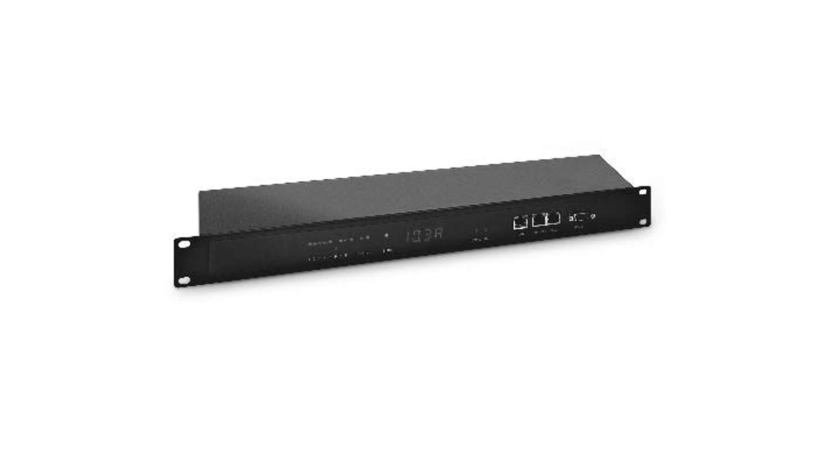

Smart PDU, 1HE, 1 Phase, 16A, 12 x C13

Quick Installation Guide|DN-95635 (Switched)DN-95636 (Outlet Monitored & Switched)
Dear Customer,
this quick start guide will enable you to start up your device. More detailed information on operating it can be found in the corresponding user manual. It is available at Digitus.info.
Security Advice
- The device must be installed only by qualified personnel according to the following installation and operating instructions. The manufacturer does not accept responsibility in case of improper use of the device and particularly any use of equipment that may cause personal injury or material damage.
- The device contains no user-maintainable parts. All maintenance has to be performed by factory-trained service personnel.
- This device contains potentially hazardous voltages and should not be opened or disassembled.
- The device can be connected only to 100 – 240 V AC (50 – 60 Hz) power supply sockets. The used power cords, plugs, and sockets have to be in good condition. Always connect the device to properly grounded power sockets.
- To disconnect the appliance quickly and safely from the power supply, the outlet supplying the appliance with power must be easily accessible.
- This equipment is designed for indoor use only. It must not be used in condensing or excessively hot environments.
- Please also observe the other instructions in instructions for proper handling of the device.
- Because of safety and approval issues, it is not allowed to modify the device without our permission.
- The device is NOT a toy. It has to be used or stored out of range of children.
- Care about packaging material. Plastics have to be stored out of range of children. Please recycle the packaging materials.
- In case of further questions, about installation, operation, or usage of the device, which are not clear after reading the manual, please do not hesitate to ask our support team.
- Please, never leave connected equipment unattended, that can cause damage.
- Only connect electrical devices that do not have a limited duty cycle. This means that in the event of a fault, all connected electrical devices must be able to withstand continuous activation without causing damage.
Installation
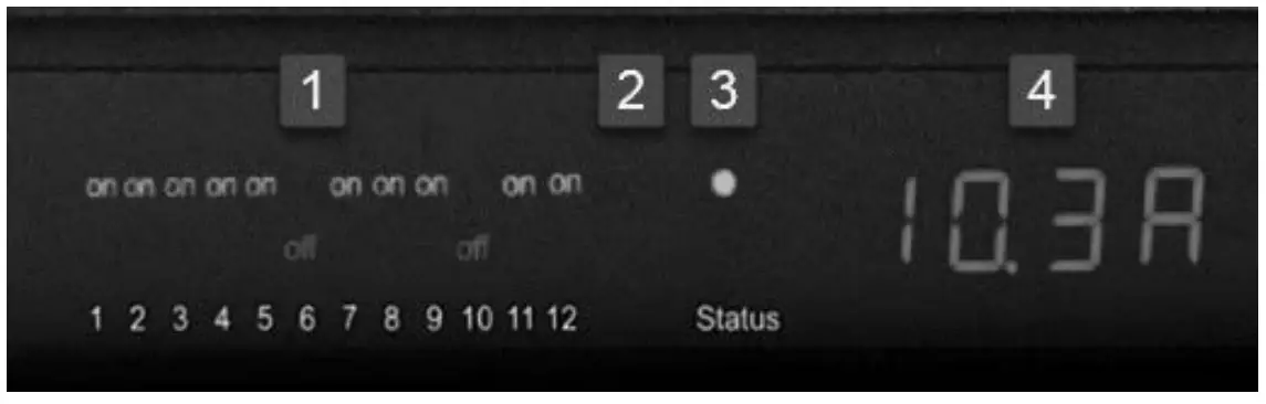
- 12 plain text displays (on/off) for the state of the outputs
- LED indicator for Over Voltage Protection (red – surge protection is inactive)
- Status LED The Status LED shows the different states of the device:• red: The device is not connected to the Ethernet.• orange: The device is connected to the Ethernet and waits for data from the DHCP server.• green: The device is connected to the Ethernet and the TCP/IP settings are allocated.• periodic blinking: The device is in Bootloader mode.
- Current power consumption (7-segment display)

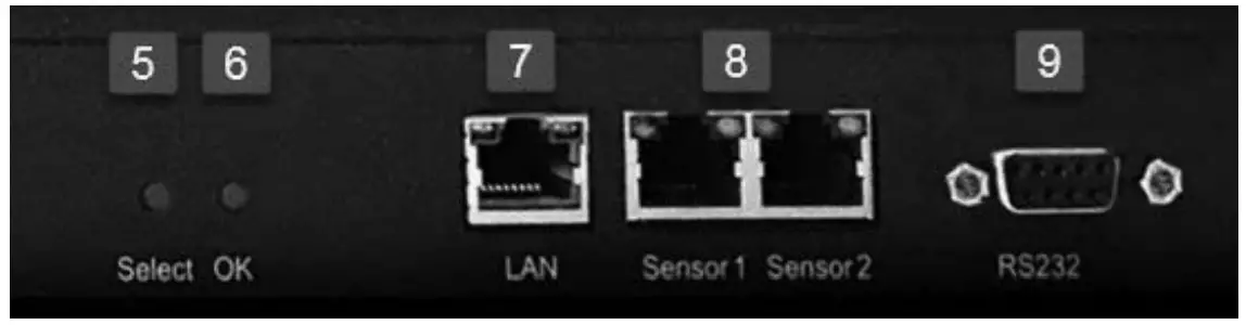
- Select button
- Ok button
- Ethernet connector (R145)
- External sensor connectors (R145)
- RS232 connector
- 10. Mains supply (IEC C20, max.16 A)
- 11. 12 x Load outputs (IEC C13, max. 16 A)

Startup the device
- Connect the power cord (IEC C19, max. 16A) to the mains supply. The cable connectors are secured as regards their type against unintentional loosening. They must be inserted up to the stop, otherwise, there is no secure connection. The plug must not wobble in the socket, or there is no tight connection.
- Plug the network cable into the Ethernet socket (RAS).
- If required, setup a serial connection to the RS232 port.
- Insert the optional external sensors into the sensor connectors.
- Connect the consumers with the load outputs (IEC C13, max. 10A).
Overvoltage Protection The device contains overvoltage protection. The protection is based on input side varistors with thermal fuse between phase (L) and neutral (N) to protect the internal electronics and power ports with failure detection (permanently triggered thermal fuse). The state of the protection is indicated on the front panel by a red flash. An invisible flash means that the protection is active, a red flash symbolizes that the overvoltage protection fails. In addition, the status of the overvoltage protection can be seen on the Webpage (HTTP) and acquired with SNMP. Each surge protection module is designed that it can derive a practically unlimited number of voltage pulses in normal installation environments. In an environment with many energy-rich surge pulses, it can result in permanent loss of function due to aging of the overvoltage protection element.
 Recovering of the overvoltage protection function can only be performed by the manufacturer of the device. In the normal case, the device will continue to work even after the failure of the protective function. A signaling via E-Mail, Syslog or SNMP trap occurs only once during operation, exactly at the moment in which the protection fails. In addition, at the start-up of the device, a message is generated, when the overvoltage protection is not active.
Connect to the TCP/IP network
Connect your device to the network by plugging in the connector cable to the Ethernet connector. The device searches for a DHCP server and requests an available IP address. Check in the DHCP server settings, which IP address has been allocated. If necessary, make sure that the same IP address will be assigned at every re-start. The status LED shines shortly orange before it turns constantly green. Your device is now connected to the TCP/IP network and ready for operation.
Set-up and using features
The web interface is the central control panel of your device (see Fig. 1). You can access it from any PC in the same TCP/IP network.
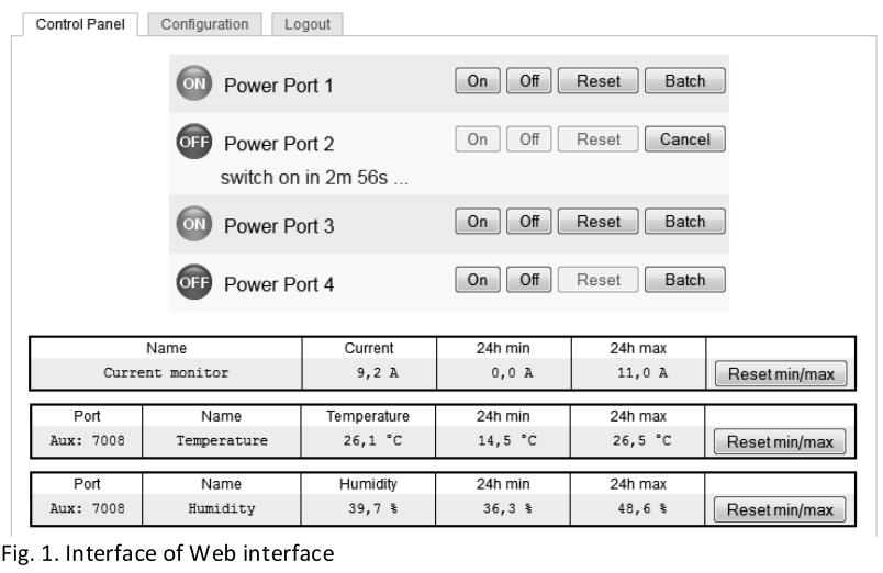
By accessing the web interface, you can
- configure all device settings and
- use all features of your device (e.g., switching power outlets or retrieving sensor values).
You can access the web interface of your device as follows:
- Open the web browser of a PC being in the same network.
- Enter the following into the address bar of your web browser: http://”device IP address”! (default: 192.168.0.2)
- Login.
In case that your device can not be found at the address entered, use our configuration program GBL_Conf.By using GBL_Conf you can
- configure all network and security settings and
- restore them to default settings.
Set-up by using the configuration program
The most current version of GBL_Conf. can be found at Digitus.info. Download and open the provided file and follow the onscreen instructions. After successful installation, please follow these steps:
- Open GBL_Conf. All found devices in the network will now appear in the left window as shown in Fig. 2.
- Double-click on the device name. You will be forwarded automatically to the device’s web interface in your web browser.

This is a Class A product. In-home environment, this product may cause radio interference. In this case, the user may be required to take appropriate measures.Hereby Assmann Electronic GmbH declares that the Declaration of Conformity is part of the shipping content. If the Declaration of Conformity is missing, you can request it by post under the below-mentioned manufacturer address. www.assmann.comAssmann Electronic GmbHAuf dem Schuffel 358513 LiidenscheidGermany
[xyz-ips snippet=”download-snippet”]