
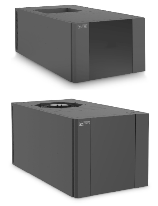
DIGITUS Top Cooling Unit
Security Information
Symbol DescriptionInstallation, operation, or maintenance of equipment before servicing, please read the manual carefully and keep in mind. Other matters on the information in this manual or equipment, the following symbols illustrate messages may appear to warn of potential danger or attention.
- DANGER indicates an imminently hazardous situation which, if not avoided, will result in death or serious injury.
- WARNING indicates a potentially hazardous situation which, if not avoided, can result in death or serious injury.
- CAUTION indicates a potentially hazardous situation which, if not avoided, can result in minor or moderate injury.
- NOTICE addresses practices not related to physical injury including certain environmental hazards, potential damage or loss of data.
Operating Precautions
When using the device, read and observe the following operating precautions. When handling refrigerant, observe all local and national regulations.
Electric shock, arc flash or explosion risk
- Use appropriate protective device for protection operation, and to comply with norms electrician.
- Equipment should be installed and maintenance personnel with innovative Itanium recognized relevant professional qualifications.
- Before installation, maintenance equipment, be sure to cut off all power.
- Use the multimeter to measure; make sure the power is turned off.
- Before turning on the power, the final installation accessories to be installed, such as a door, cover, fastening device and the like.
Or it can result in death or serious injury.
- Note hands, clothing, and jewelry away from moving parts. Before closing the doors and starting the device, check if a foreign body device.
- Dangerous equipment or personnelEquipment should be installed and maintenance personnel with innovative Itanium recognized relevant professional qualifications.
The risk of tipping equipment
- There must always be at least two people moving or rotating device.
- Be sure to face the front and back of the device pushing, pulling or rotation. Facing side of the device cannot be pushed, pulled or rotated.
- Slowly moving the device through the uneven surface or threshold.
- When the device is stationary, supporting feet lower to the floor.
- When the device is in the final position, the lower supporting legs, and with the adjacent cabinets securely.Or it can result in serious injury or equipment damage.
Dangerous equipment or personnel
- Before operating the device, make sure that the equipment or device inside the spare parts and tools has been removed.
High-pressure refrigerant or equipment damage
- Use only R410A refrigerant.
- Brass must support a minimum working pressure of 55 bar.Or it can result in serious injury or equipment damage.
Product Description
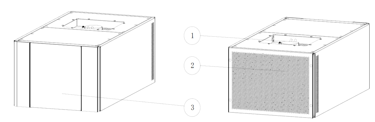
- Outdoor fan (Air outlet)
- Outdoor air inlet
- Seal panel

- Outdoor fan
- Condenser
- Compressor
- Electrical box
- Indoor fan
- Evaporator
Device DescriptionThe compressor – the main role of the refrigeration system through the evaporator for evaporating low pressure refrigerant gas compressed at room temperature to a temperature high-pressure refrigerant gas, increasing its temperature condensation into the (outer chamber) is liquid condensed in the condenser. The key is the core component of the refrigeration system.
- High-voltage switch – after the refrigerant pressure in the system rises to a certain value, high-voltage switching operation, the alarm is transmitted to the controller.
- High pressure sensor – detecting high side pressure of the refrigeration system, and transmitted to the controller.
- Filter drier – protection refrigeration systems, water filtration systems, solid acid and impurities.
- The expansion valve – valve electronic expansion valve, the refrigerant flow rate regulator.
- Evaporator – refrigerant evaporated inside the evaporator absorbs heat, gas flow through the outer surface of the evaporator heat absorber is cooled.
- Low pressure sensor – the low-pressure side refrigerant pressure detecting system, and transmitted to the controller.
- Fan – means for driving an air flow through the air conditioning cycle.
- Controller – logic control center of the machine, the operation of the automatic control equipment, alarms, details refer to the section controller. Located outside the electrical box.
- Touch screen – computer interaction window, only to see the equipment running through the display, it can also be related to the setting operation.
Product Size
| Product number | Width (mm) | Depth (mm) | Height (mm) |
| DN-97330 | 600 | 1100 | 390 |
| DN-97331 | 600 | 1100 | 521 |
Environmental Requirements
Operating Environment
| Project | Indoor side | Room outer side |
| Temperature | -10 °C ~ 55 °C | -20 °C ~ 45 °C |
| Humidity | 20 % to 80 % | – |
|
Altitude |
Altitude <1 000 m
Greater than 1 000 m Derating about 6 % / one thousand meters |
|
| Power supply | Single-phase or three-phase 380V 220 ~ 240VFrequency
50Hz ± 2HzOr 60Hz± 2H |
Storage Environment
| Project | Claim |
| Surroundings | A clean (no dust), well-ventilated |
| Temperature | -40 °C ~ +60 °C |
| Humidity | 5 % RH ~ 95 % RH non-condensing |
| Duration | A total of not more than six months, more than six months
to be re-calibrated performance |
Installation and Commissioning
Installation Preparation
Tools to prepareWrench, socket wrench, Phillips screwdriver, slotted screwdriver, diagonal pliers, needle nose pliers, the word ladder, tape measure, flashlight, marker, truck. Insulated gloves, wire strippers, insulating tape, crimping pliers, clamp.Material preparationDrain line, power supply cable.Site PreparationMounting plate: air-conditioning sheet metal plate or rack load capacity is enough to bear weight without deformation apparatus, distortion.Interior: smooth out of the wind inside the device, not within 300mm from tuyere is blocked, the indoor side heat well, a good seal. Access to rear line arrangement.Outdoor: smooth out of the wind, far away from people stay. Outdoor wind direction should not be opposite to the monsoon. If direct sunlight, should be done protection. Prevent high temperature and humidity, dust, air enters the device acid. Installation position and stay close to the obstacle distance of at least 500mm. Ground clearance of not less than50mm.
Installation GuidelinesEquipment must be in good condition. Sealed from the outside.
Unpacking Inspection
Out of the box before check the packaging for damage, if there is damage, please contact the carrier.Carefully remove the packaging and check whether there are internal devices scratches, impact, if any, please contact the carrier.The packing list an inventory of accessories are complete, if not complete, please contact the supplier.– Remove the front and back packaging must ensure that the device remains upright, not tilted or tipped over.
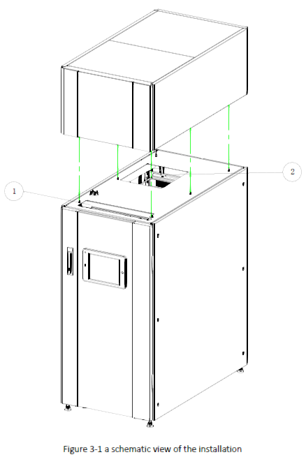
Device Installation
Mechanical Installation
- The sealing inlet airflow port and outlet airflow port.
- At the top of the cabinet, openings are made according to the size and position of the air inlet and outlet in the air-conditioning room. The air conditioner is installed at the top of the cabinet to be fixed. Fasten with fasteners such as screws and nuts.
- Drain connected to the drain assembly in the apparatus, the drain connected to the drain drain assembly, with hose clamps firmly fixed, and the other end to a suitable drain through the drain. If using outdoors, you cannot take drain assembly and drainage pipes, drainage equipment directly at the outfall.
- Supply air port
- Return air port
Electrical Installation
When electrical installation, note the following requirements:
- All Power cord, connect the control line and ground must comply with local regulations.
- A full load operating current of the unit, check the unit nameplate. Cable size should meet the electrical requirements.
- The need to connect a cable is: power lines, signal lines.
- Main power supply unit requires the same rated power and the nameplate.
- The cable can be selected only copper cable, wiring to ensure that all connections are secure.
- The electrical installation must be done by a professional electrical installer.
- Before connecting circuit, an input power source voltage, and the power supply has been disconnected is determined with a multimeter.
After completion of the electrical installation, you need to check the following:
- Same rated supply voltage and the voltage on the rating plate.
- The crew did not open electrical circuit, short circuit.
- The ground cable connection device is connected.
- The power supply circuit breaker and fuse rating to meet the needs of the unit.
- If the monitoring cable, check the monitor cable is connected.
- Check all cables, connectors have been tightened, without loosening the fixing screws.
Start-up Procedures
Upstream circuit breaker is closed air-conditioning, the controller start.
Control System
Interface Description
Note: Screen is optional.The program interface is divided into homepage, menu page, alarm page.
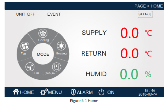
Automatically enter the home page when you are on power. Or automatically return to the home page if the interface is not operated for a long time.(21:10/2018-03-24) Time/date. Show current date, you can change the time in the clock Settings.(Home/menu/alarm/boot) Menu options, click the corresponding option to enter the corresponding menu page.The “home page” option currently displays the embedded background mode, representing the current page as the home page. Other pages are similar, and the post is not repeated.(Temperature 0.0 °C) shows that temperature sensors to detect real-time temperature.(Humidity 0.0 %) shows the real-time humidity detected by humidity sensor. (The unit state shutdown) shows the current operating state of the unit and the “boot” state.(Alarm) This will scroll to show all the current alarms.(Censored) When there is an alarm, there will be a warning sound, click the noise to eliminate the alarm sound.(Operating state refrigeration and heat dehumidification humidifier) various functional operation status.
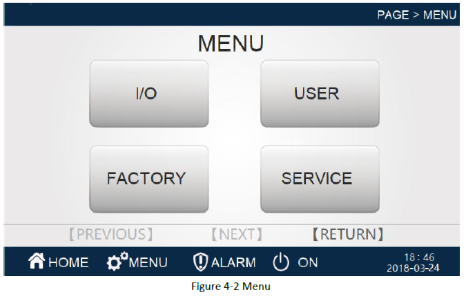
You can enter the menu page at other page point menu.(I/O) Click to enter the input output page, including all digital input output information and analog quantity input and output information.(User Settings) click to enter the user Settings page, including the parameters set by the user.(Factory Settings) click to enter the factory Settings page, including all factory Settings.(Maintenance Settings) click to enter the maintenance Settings page, including all maintenance Settings parameters.
Alarm
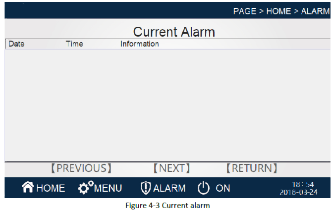
Under this menu, you can view all alarms that exist in the current unit.(Trigger date) the exact date of the alarm.(Trigger time) The timing of the alarm.(Alarm content) Warning.(Return) The return key is returned to the previous page.(Next page) Page turn option, click to enter the history alarm page.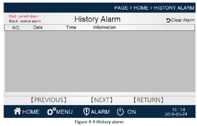
Under this menu, you can view all the uncleared alarms that have occurred before the current crew.(Serial number) Alarm number.(Date) The exact date of the alarm.(Time) The timing of the alarm.(Alarm content) Alarm content.(Return) The return key is returned to the previous page.(Next page) Page turn option, click to enter the current alarm page.(Clearance alarm) Click to clear all history alarms
Input / Output 1
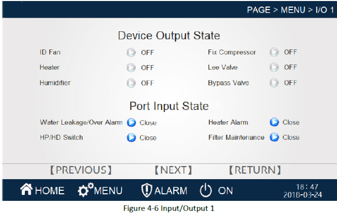
Under this menu, you can view the current unit number input state and digital output status. When the output status of the device is blue, the device is in the output state and the device is in a non-output state when the color is gray. When the port input state is blue, the port is entered into a closed state, and when the color is gray, the device is disconnected.(Return) The return key is returned to the previous page.(Next page) Page turn option, click to enter the input output 2 page.
Input / Output 2
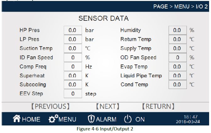
Under this menu, you can view the current unit simulation input and output values.(Temperature and humidity curve) Click to enter the temperature and humidity curve interface.(Pressure curve) Click into the pressure curve interface.(Return) The return key is returned to the previous page.(Previous page) Turn page option, click to enter the input output 1 page.
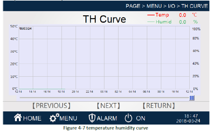
Temperature humidity curve
Pressure curve

User settings
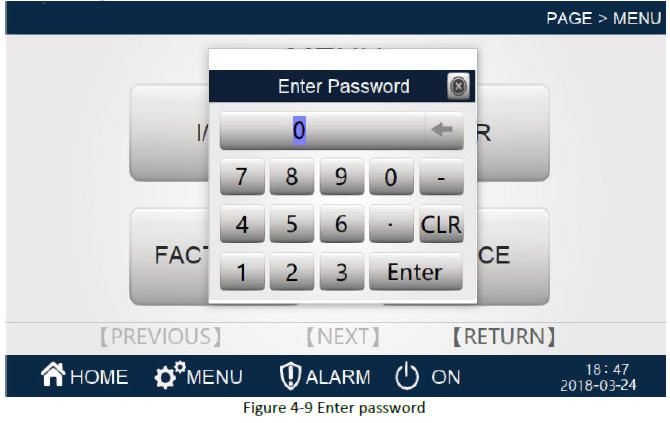
Enter password “999900”. Enter the Settings page.
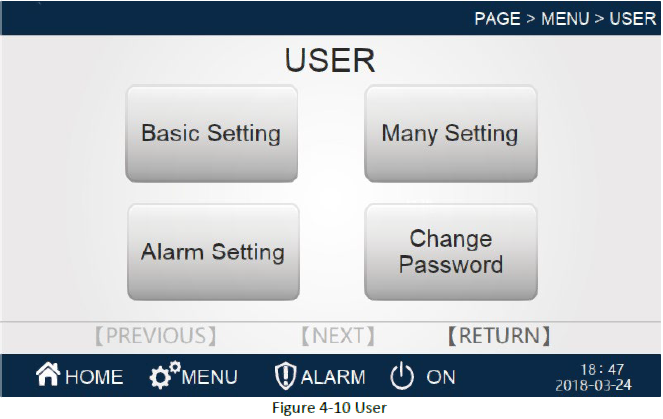
Click the user Settings option on other page points to enter the user Settings page.(Basic setting) Click to enter the basic Settings page, including temperature and humidity Settings.(Many setting) Click to enter the comprehensive Settings page, including date time, monitoring address, etc.(Alarm setting) Click to enter the alarm Settings page, including alarm value Settings, alarm property Settings.(Change password) Click to enter the change password page and change the user password.
Basic settings

(Temp Setting 0.0 °C) Set the temperature setting value, that is, the expected indoor temperature.(Humid Setting 0.0 %) Set the humidity setting value, that is, the expected indoor humidity.(Temp Band 0.0 °C) Set the temperature range, that is, the deviation of the set point of the temperature, to ensure that there is a deviation in the temperature point of the device starting and stopping, and it will not stop frequently during the partial load. Set temperature ranges compatible with frequent start-stop and allowable temperature fluctuations.(Humid Band 0.0 %) Set the humidity range, that is, the deviation of the humidity set point, to ensure that there is a deviation between the starting and stopping humidity point of the equipment, and it will not stop frequently during the partial load. When setting the humidity range, it is compatible with frequent start-stop and allowable humidity fluctuations.(Heat on band 0.0 °C) Set the heating opening deviation, that is to achieve the temperature deviation after the basic conditions of heating.(Heat off band 0.0 °C) Set the heat closing deviation, that is, to meet the basic conditions of thermal shutdown after the temperature deviation.(Control mode return air) The temperature control is based on the risk control system, and the air supply can be selected.(Repower startup) Turn on the incoming call function.(Return) The return key is returned to the previous page
Many setting
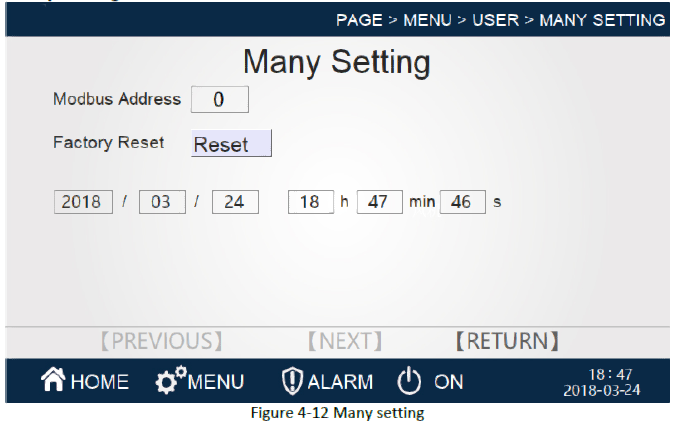
(2018 Year 03 month 20 day 13 hour 22 minute 52 second) Date and time, you can set the current date and time.(Modbus address 0) Monitor address, you can set the monitor address of the controller.(Restore factory reset) Factory setting reset.(Return) The return key is returned to the previous page.
Alarm setting

(High temperature alarm 0.0 °C) High temperature alarm value, the return air temperature exceeds the high temperature alarm set value and then the alarm. Click the number to set.(Low temperature alarm 0.0 °C) Low temperature alarm value, the return air temperature is lower than the low temperature alarm set value and then the alarm. Click the number to set.(High humidity alarm value 0.0 %) The high humidity alarm value, the return air humidity exceeds the high humidity alarm set value after the alarm. Click the number to set.(Low humidity alarm value 0.0 %) The low humidity alarm value, the return air humidity is lower than the low wet alarm set value after the alarm. Click the number to set.(Return) The return key is returned to the previous page.
User change password

(user password Settings******) click the text box to change the password.
User password confirmation
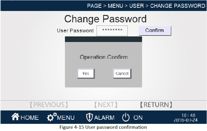
(Password confirmation) can be changed after entering the new password.
Troubleshooting
Common Fault Alarm Phenomenon and MeasuresAir conditioning failure mainly for refrigeration system failure, control system failure, the ventilation system failures and communications failures, some of Common symptoms and treatment recommendations Table 5-1 Common alarm phenomenon and measures.
| Symptom | Possible Causes | Responses |
| The unit does not start | The unit is not powered on | Check the input power supply apparatus, the wiring is solid |
| Power sequence is wrong | Check the phase sequence power and wiring | |
|
Compressor overload |
Thermal overload |
Check the air conditioning Refrigerated space Insulation and sealing the case, the necessary Time Plus equipment |
| Excessive refrigerant system | Excess refrigerant discharged within the system | |
|
Compressor own fault |
Compressor axle, the motor coil insulation in question must be replaced compressor | |
| Supply Voltage Value | Negative power supply voltage instability factor | |
| Compressor loose wiring | Good re-tighten the compressor terminal | |
| High pressure protection alarm | Pressure protection switch fault | Replace the pressure protection switch |
| Expansion valve is too loose, | Appropriately adjusting the opening degree of the expansion valve |
| The expansion valve bulb failure or incorrect mounting position | An expansion valve replacement, and proper installation position bulb | |
| Summer too much refrigerant perfusion | Remove excess refrigerant, the high pressure in the control 2.3~ Between 2.8 Mpa | |
| Outdoor condenser fouling | Cleaning the surface of dust and dirt condenser | |
|
Axial fan does not turn |
Check axial fan static resistance and the grounding resistance, such as fan coil burning should be replaced; | |
| Systems non- condensable gases mixed with | Height from the system gas discharge portion, the system re- evacuated if necessary, charge fluoride work | |
|
Fan overload |
Airflow is too large |
Check the filter installation, whether to select an error windshield |
| Voltage is too low | Check input power | |
| Fan motor winding fault | Check whether the motor windings normal | |
|
Low- pressure protection alarm |
Low Voltage Protection Switch Fault |
Replace the low protection switch |
| Expansion valve is too small | Appropriately adjusting the opening degree of the expansion valve | |
| The expansion valve bulb failure or incorrect mounting position | An expansion valve replacement, and proper installation position bulb |
| Lack of refrigerant in the system | Tim refrigerant charge control in the low voltage 0.9 ~ 1 Between Mpa | |
| Filter clogging dried | Replacing the filter was dried | |
| Evaporator frosting | Respond to the evaporator to defrost | |
| Evaporator surface fouling | Cleaning of the evaporator evaporation surface | |
| Air volume is too small | Check that the air filter is clogged and a return air conduit | |
| Low-voltage protection delay is not set correctly | Readjustment of the low-pressure time delay |
Hereby Assmann Electronic GmbH, declares that the Declaration of Conformity is part of the shipping content. If the Declaration of Conformity is missing, you can request it by post under the below mentioned manufacturer address.
www.assmann.comAssmann Electronic
![]()
References
[xyz-ips snippet=”download-snippet”]