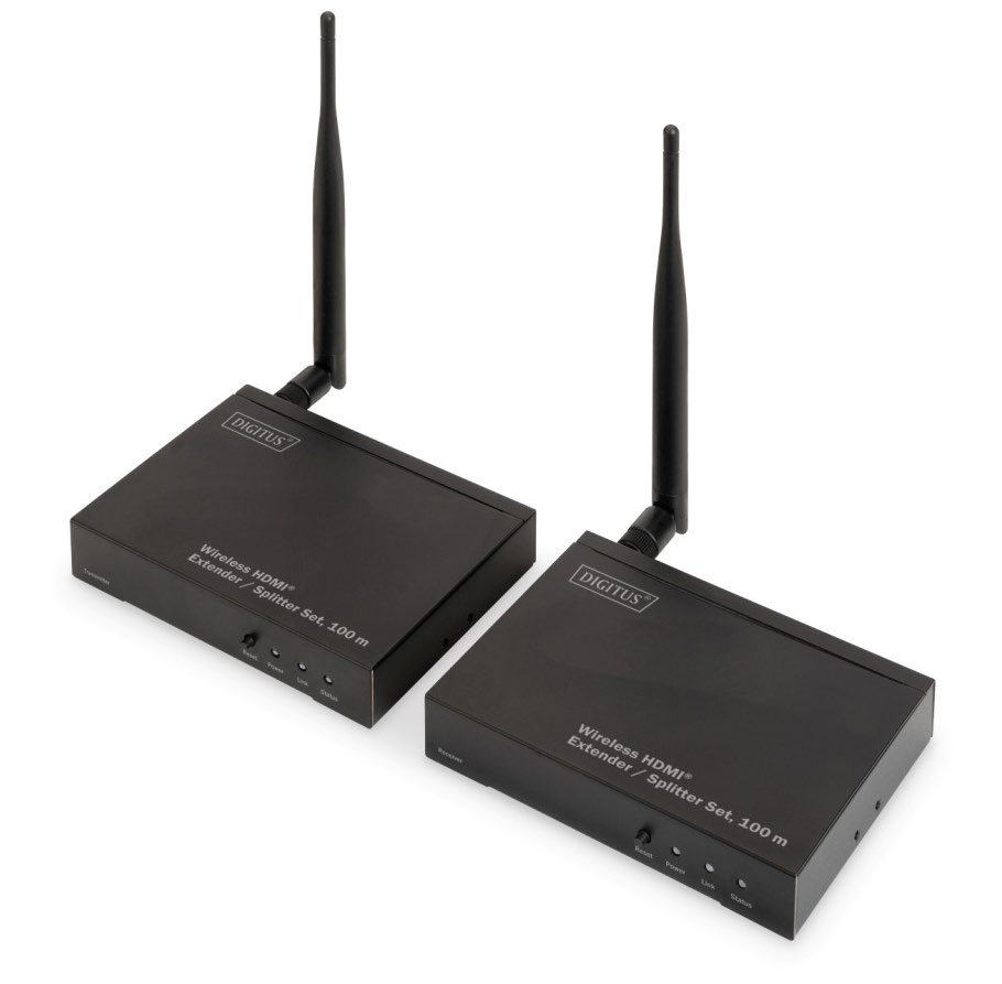

Digitus Wireless HDMI Extender / Splitter User Manual
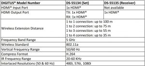
DS-55314 – Set: 1x Sender Unit (TX), 1x Receiver Unit (RX) DS-55315 – 1x Receiver Unit (RX)
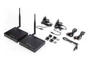
Package Content DS-55314:
- Main Units: 1x TX, 1x RX
- 2x Power Adapter (DC 5V/2A)
- 4x Mounting Bars
- 1x IR TX Cable, 1x IR RX Cable
- 1x 3.5 mm Male to Male Cable
Introduction
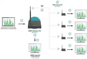
The Wireless HDMI® Extender / Splitter Set wirelessly transmits your high-resolution HDMI® video and audio signals up to a distance of 100 m (1:1 connection, unrestricted view). The operation of the Extender Set is kept very simple by real Plug & Play, you connect source and receiver device to the set and can start immediately. In addition, you can control the devices at the location of the signal source with your existing infrared remote control from the receiver module. Two infrared connection cables are included in the set, which you can connect to the transmitter and receiver. Furthermore you have the possibility to extend this set to up to 4 receivers (DS-55315), these are optionally available. For example, you can output the signal from a set-top box to up to 4 different TV sets simultaneously and even control the box from any receiver. Save yourself the trouble of laying HDMI® cables and use this easy-to-use Wireless HDMI® Extender / Splitter System.
Features
- Wireless transmission of HDMI® signals over a distance of up to 100 m (1:1 connection, unrestricted visibility)
- The set can be extended to up to 4 receiver units (DS-55315) and offers splitter functionality with additional receivers
- Supports point-to-point and multicast transfer
- Distribute your HDMI® signal to up to 4 TVs/monitors
- IR input and output for transmitting remote control signal to source device
- Additional HDMI® output (loop-out) on the transmitter module for connection of an external monitor
- Plug & Play – no software or drivers required
- Transmission of HDMI® signals in Full HD with max. resolution of 1080p / 60 Hz
- Supports 2D signal processing
- HDMI® version: 1.3
- HDCP version: 1.3
- Transmission latency: 150 – 200 ms
Frequency Range & Maximum Transmit Power
![]()
Interfaces Introduction
Receiver Unit:
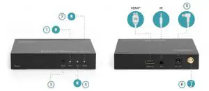
Sender Unit:
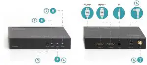
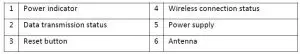
- HDMI® In: Connect to input sources (PC, Notebook, Set-Top-Box, SAT Receiver, etc.) via HDMI® cable
- HDMI® Out: Connect to output devices (TV, monitor, etc.) via HDMI®
- Power Supply: DC 5V/2A In
- HDMI® Loop Out: HDMI® Loop Out port for local TV/display
- Reset: Settings reset button
- IR In: IR signal input port
- IR Out: IR signal output port
- Power: Power LED indicator
- Link: No Connection: Continuous lightning Connected: Quickly flashing light
- Status: No video signal connection: Slowly flashing light Video signal connection: Quickly flashing light
Important: If long press “Reset” button for 10 seconds on the receiver unit, the receiver setups will be erased. User can rebuild the settings by following “Installation for DS-55315 (receiver unit)”DS-55134 Sender and Receiver units are default paired. No settings needed.
Installation for DS-55314 (Set)
- Install mounting ears if needed
- Connect Sender (TX) unit with HDMI® source and IR TX cable
- Connect Receiver (RX) unit with HDMI® TV/display and IR RX cable
- Supply power to both Sender and Receiver units
- The Power LED on both sides will light on
- The Status LED flashes slowly and waiting for pairing
- Display of the receiver shows “Searching TX”
- When Link and Status LED flash quickly, installation is completed
- If a local display is needed, connect another screen to the Sender unit anytime
Note: 3.5mm audio cable is used only when Sender and Receiver pair settings is needed
Installation for DS-55315 (additional Receiver)
- Find 3.5mm male to male audio cable from accessory
- Connect the sender and receiver with the audio cable via IR port
- Connect sender unit with input device, connecting the receiver unit with a display
- Supply power on both sender and receiver Long press the “Reset” button for 10 second on the Receiver. The display shows “searching TX”
- Short press the “Reset” button on both sender and receiver unit to match the sender and receiver
- The Link and Status LED both will flash quickly. Settings completed
Note: If you wish to connect more receivers, please repeat above steps to match up to 4 receivers
Connection Diagram
Example 1:1 connection:

Example 1:4 connection:

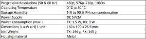
Specification
Note
- The transmission distance in obstructed areas cannot be determined generally and depends on the specific environment.
- Walls, glass, etc. can cause the signal coverage to be shorter or disrupted.
- The max. transmission distance (100 m) is reliant on optimum conditions. Other devices in the vicinity using the 5 GHz band (WiFi networks or other wireless video transmitters) can lead to interference and a significant decrease of the transmission distance or picture stability.
- Make sure your input AC voltage is compliant to the adapter specifications.
- Only use the power adapters provided with the DS-55314, DS-55315.
- If you use your own adapter, make sure the power output is 5V DC, 2A.
Troubleshooting

Important safety instructions
Please read the following safety instructions carefully before installation and operation:
- Observe all warnings and instructions concerning this device
- Do not expose the device to rain, moisture, vapours or liquids
- Do not insert any objects into the device
- Do not attempt to repair the unit yourself or open the cabinet. Risk of electric shock!
- Ensure adequate ventilation to prevent damage due to overheating
- Turn off the power supply and make sure the environment is safe before installation
- In the event of thunderstorms, there is a risk of lightning strike and damage to connected electrical equipment due to overvoltage
- Do not install this device during a thunderstorm
- Disconnect the device from the connected electrical appliances during a thunderstorm
- Use the device inside buildings only
- Return the device to your dealer in case of repair
- Dust, moisture, vapours and strong cleaning agents or solvents can damage the device
- Disconnect the device from the power supply and the connected devices before cleaning
- Clean the device with a lint-free cloth
- To completely disconnect the system from the mains, the power supply unit must be unplugged from the socket. The power supply unit serves as a disconnecting device for separating the system from the mains.
![]() The Adopted Trademarks HDMI®, HDMI High-Definition Multimedia Interface™, and the HDMI® logo are trademarks or registered trademarks of HDMI® Licensing Administrator, Inc. in the United States and other countries. All other trademarks, registered trademarks, or service marks are the property of their respective owners.
The Adopted Trademarks HDMI®, HDMI High-Definition Multimedia Interface™, and the HDMI® logo are trademarks or registered trademarks of HDMI® Licensing Administrator, Inc. in the United States and other countries. All other trademarks, registered trademarks, or service marks are the property of their respective owners.
Hereby Assmann Electronic GmbH declares that the Declaration of Conformity is part of the shipping content. If the Declaration of Conformity is missing, you can request it by post under the below mentioned manufacturer address.
www.assmann.comAssmann Electronic GmbHAuf dem Schüffel 358513 LüdenscheidGermany

References
[xyz-ips snippet=”download-snippet”]