DH-B2 BGA Rework Station
SHENZHEN DINGHUA TECHNOLOGY DEVELOPMENT CO.,LTDDH-B2 BGA Rework Station ManualAdd4th Floor, Building 6B, Shengzuozhi Industrial Zone, Road Xinyu, Xinqiao, Shajing, Bao’an area, Shenzhen, China Websitewww.sinobga.com Tel+86-755-29091633 29091822 Fax: +86-755-29091622 E-mail:service@dinghua-bga.com1
Company profileSHENZHEN DINGHUA TECHNOLOGY DEVELOPMENT CO.,LTD is a professional manufacturer of welding equipments.Our products: bga rework stations,automatic soldering machines,automatic screwdriving machines,welding kits and SMT materials etc.Our mission: “Research as basis, Quality as core, Service as guarantee” . Our goal: “Professional equipment, quality and service”To ensure the quality, Dinghua was the first to pass ULE-MARKCCCFCCCE ROHS certificates. Meanwhile, to improve and perfect the quality system, Dinghua has passed ISO GMPFCCAC-TPAT on-site audit certification.Science and technology are the primary productive forces, with over years of hardworking, Dinghua has owned core technology of temperature controlled and 38 patents and finished the development and production of manual, semi-auto and automatic series and realized the second revolution from traditional hardware combination to integrated control.Our products have been exported to Europe , America, Southeast Asia, Australia, Africa, the Middle East, Taiwan and more than 80 countries and regions and established the relatively sales network and terminal services system.We are becoming the pioneer and guide of SMT welding industrial and our products have been applied in individual maintenance,industrial and mining enterprises,teaching and research work,military manufacturing industry and aerospace industry and so on, which has treed good reputation among users.We believe:your successes are our successes,let’s work together and build a better future!Installation of BGA rework stationInstallation sitesIn order to ensure that the useful life of BGA rework station, installation of repair station must meet the following conditions: 1Away from flammable and explosive materials 2Do not splash water or other liquids 3Well-ventilated , dry place 4Stable , flat areas less susceptible to vibration 5Place less dust 6 Prohibit Placing heavy objects on top of the control box 7Without the affect of air-conditioners,heaters and fans 8Reserved for 30cm to move and rotate around the upper for the back of rework station2
()Power RequirementsUse a smaller power supply voltage fluctuation Voltage fluctuations: 220V±10 Frequency fluctuations: 50Hz±3Safety Precautions of rework station1 Do not use fans or other devices directly to the repair station hair when it works, otherwise it will lead to negative differential heating plate surface , burn the workpiece.2When turned on, high-temperature heating zone can not be any direct contact with the object , it may cause fire or explosion ,and the PCB workpiece should be placed on the PCB support shelves.3Do not shake rework station , and move gently 4Do not touch the high fever area , otherwise it will burn 5 When turned on, do not use the flammable spray , liquid or flammable gas near the repair station. 6Do not try to modify rework station , otherwise it will cause fire or electric shock. 7Electrical box has the high-voltage components , do not attempt to disassemble 8If the metal objects or liquids fall into the repair station when it works , immediately disconnectthe power , unplug the power cord until the machine to cool down , then completely remove litter , dirt ; if dirt left ,there is odor when reboot. 9 When abnormal heating or smoking,immediately disconnect the power , and inform the technical service to repair.It needs to disconnect the wires between the electrical boxes and machine parts,and have to hold the plug,otherwise it leads to poor contact ,and does not work. 10Note that the repair station not to press or run over other electrical equipment or power lines or communication cable , and it may cause device malfunction or cause fire or electric shock. 11Before use the rework station, you must read this manual carefully3
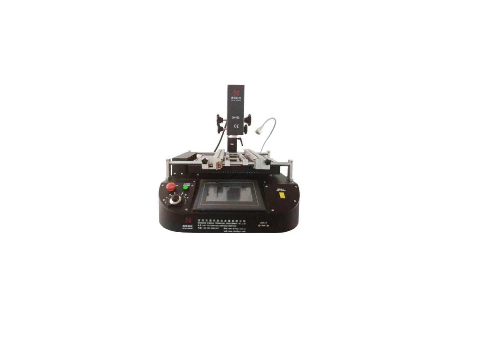
Structures and specificationsStructuresTop air heaterUpper air heater Hot air nozzleLower hot air heater Cooling fanTop air reflow adjustTouchscreenUSB port
Limited barUp/down adjust handle Front / back adjust handle LED light PCB table Universal fixtureIR preheating Temperature sensor
4
Features
Name
Functions
Use ways
Limit barUp/down adjust handleFront and back adjust handleLED lights PCB tableUSB port
limit the lowest position of the upper heating Adjust the upper heater up / down Adjust the upper heater frontward / backward
Rotate to the right place Rotating the handle Rotating the handle
Lighting equipment at work
Press the button
Hold or fix pcb board on the machine
For future system update or Insert USBdownload
Touch screenTop air reflow adjust Cooling fan Temperature sensor Universal fixture Hot air nozzle Bottom IR diode tube heat Lower air heater
Data storage system platform
Adjust air speed to prevent
tiny bga from movement Rotating
when heating
Cross flow fan, cooling pcb
and machine after heating
Detect actual temperature of solders when heating
Connected with sensor wire
To hold or fix pcb board which unregular shape.
Fixed with knob
Nozzles size 2mm bigger than chip size, focus air.
With magnet
Bottom large size IR diode
tube pre-heating zone with Preheating for pcb board
glass guard
2nd hot air heater
IR preheating
For PCB being preheated
Top air heater
Top hot air heater
5
Specification
Total Power
4800W
Top heater
800W
Bottom heater Power
2nd 1200W, 3rd IR diode tube heating 2700W AC220V±10 50Hz
Lighting
Taiwan led working light, any angle adjusted.
Operation mode
HD touch screen, intelligent conversational interface, digital system setting
Storage
50000 groups
Top heater movement
Right/left, frontward/backward, rotate freely.
Positioning
Intelligent positioning, PCB can be adjusted in X, Y direction with “5 points support” + V-groov pcb bracket + universal fixtures.
Temperature control Temp accuracy
K sensor, close loop ±2
PCB size
Max 500×400 mm Min 20×20 mm
BGA chip
2×2 mm – 80×80 mm
Minimum chip spacing
0.15mm
External temper sensor
4pc
Dimensions
650*700*650mm
Net weight
48KG
Special feature:Bottom Newest heating type, diode tube heating, temperature rising and down rapidly, more precise. Four External temperature sensors detect all round temperature of bga at the same time, enablestemperature monitoring and accurate analysis of real time temperature profile. With top air reflow adjust function, prevent small bga from movement when heating. Double shadowless led lights, observe bga melting clearly when heating. Any size of nozzle can be custom if need. With vacuum tube, pick up the bga chip conveniently after desoldering. With USB 2.0 interface, can be connected with a computer or mouse, screenshot temperature curve orsystem update. Real-time settings and actual temperature profile display can be used to analyzed and correctparameters. K type close loop control, temperature accuracy will be on ±2°C High power cross flow cooling fan, prevent the PCB from deformation.6
Sound hint system: there is voice reminder 5s-10s before the completion of heating, to get the operator preparedsecurity measure: overheat guard and emergency stop functionHumanized design:Upper heater can move up/down, front/back, rotate freely Lower heater can move up/down to keep best distance with pcb. Strong sense of thermometer, temperature measurement more accurate PCB clamp (V-groove) with universal fixture, suitable for all kinds of BGA. it can set 8 segments heating, massive storage of temperature profiles With different size of nozzles, easy replace and use, customized is available. Colorful buttons in English and chinese, easy recognize and use. CE certification, automatic power-off protection device when emergency happens.Operations:1Preheat Preheat the PCB board and BGA chip, and the temperature of constant temperature oven is set at 80 -100 , for 4-8 hours to remove internal moisture of the PCB and BGA, to prevent the burst phenomenon when heating. 2Remove Place the PCB board into the bracket on the repair station,and select the appropriate hot air reflow nozzle,and set the appropriate soldering curve,press the open button until it finishes,and then move the hot air manually,to suck the BGA chip away with the vacuum suction pen. 3Clean-up welding The BGA pad clean-up , one with desoldering line to drag flat, the second with iron; Best to remove the tin a short time after the BGA removed , then BGA has not completely cooled , and the temperature difference make less damage to the pad;use the flux can improve the activity of soldering tin,better to clean the soldering tin. Particular attention not to damage the PCB pad,and in order to ensure the reliability of BGA solder, when the cleaning pad to make use of some of the solder paste residues with more volatile solvents , such as plate washer water, industrial alcohol. 4BGA re-balling Wipe the paste flux equably with the brush pen on the BGA pad, choose the right steel mesh, and then plant tin beads by the re-balling kit on the right pad. 5BGA tin beads welding Heat the bottom heating zone of BGA re-balling station and then weld the tin beads on the pad. 6Besmear flux Wipe the paste flux with the brush pen on the PCB pad. If you wipe so much, it will cause connected welding, on the contrary, it will cause null welding. In order to wipe off dust and impurity of tin balls, and enhance welding effect, the welding paste must be wiped equally. 7Place the BGA chip7
Place the BGA chip on the PCB board with manual alignment and silk-screen borders, meanwhile the tension of the solder joint when melt will have a good self- alignment effect. 8Weld First, put the PCB board which is pasted with BGA chip on the positioning stand, and then move the hot wind head to the working place. Second, choose the appropriate backflow nozzle and set right welding temperature curve, start heating, open the switch, and then run the welding process. Besides, after the welding process is finished, you have to cool the BGA by the cooling fan. Hoist the upper hot wind head and make the bottom of hot wind nozzle apart from the surface of BGA 3-5mm, and stay 30-40 seconds, or, you can move the hot wind head after the starting switch is put out, withdraw the hot wind head.Finally, take away the PCB board from the heating zones. (1) null welding Because of counterpoint by hand will cause deviation between chip and welding plate, surface tension of tin ball will make BGA chip and welding plate in the process of automatic correction. Once heating, BGA falls not evenly, which cause the chip drops not evenly.If stop reflowing at this time, the chip will not fall normally,which will cause th phenomenon of empty welding and false welding.So you need to extent time of third forth temperature zones or add the bottom pre-heating temperature to make ,the tin balls meltdown and drop evenly.(2) short circuit When the ball reached the melting point,it is in a liquid state , if too long or too high temperature and pressure,it will destroy surface tension of solder balls and the supporting role, resulting in short-circuit phenomenon when reflows,the chips fall entirely on the PCB pads the , so we need to appropriately reduce the heating section of the third and fourth soldering temperature and time , or reduce the bottom of the preheat temperature.Note: In normal use rework station it will produce small quantities of bad smelly, in order to ensure comfortable, safe and healthy operating environment, pls keep indoor and outdoor air flow.8
Procedure setting and usageIntroduction of touch screen operation1. Switch on the power, the BGA rework station can connect with electricity.The home page of touch screen will appear the interface like the following picture, and then you can choose the language interface as required.2When we choose Chinese, it will appear the working interface like the following picture:9
3Input password, then click to enter
.
Click the button of “current curve”
, enter “START”
to
operate the heating lines we need.They are seperately target temperature, onstant temperature time,and the speed of heating ( the speed of heating with /SEC calculation).
10
Three-zone tempertures can be set 6 levels of variable and constant temperature controls.If need,you can change the related parameters,but it’s not saved,just can heat it with this line. If saveing is necessary, please refer to relative information of ingredient settingIfthe temperature curve doesn’t meet to the needed welding temperature; please press the return
button
, returning to the main Interface.
3. Press”Curve Selection”
,it will show the fllowing interface after entering.
11
In this interface, the temperture can be changed and saved.User can set the heating temperture, the constant time and the heat speed according to the requirements of the production process. The machine can be mass storage temperature curve.User can store a a variety of manufacturing process parameters in the system.when replaceing of the production process, direct call to the parameters saved in the system, equivalent to formulation saved in the system.There are different heating temperature with different products,it can save various kinds of paraments in the different formulation,and it will be easy to use it when changed the products,not need to change many paraments.It can click the line name to choose the right formulation directly.
If have to input new parameter, click the button of “curve choose” on the numerical place, the input button will appear.
, and then click
12
Input the parameter you need, press”ENTER” key
.When temperature parameters
Settings of these three temperature zones are finished, click “save curve”, then all parameters you have set are all saved.
And it also can be changed and saved by “curve chooses”.
Click `Start’,the whole station starts to heating,and the working curve is showing the current parameter and it will also clear the previous curve showed on screen.The whole heating will complete until the upper setting temperature or the upper part of the heating rate is zero,and just the machine stops running,with the alarm ringing, if the cooling vacuum interface has been set up within the cooling and vacuum state, then these two output also work.if click `stop’ in the normal operation process, the machine will stop heating.And click ‘Keep’, the button appears as flashing,showing the machine entering the temperature kept status,and the whole heating temperature will keep the current temperature constant working,until click the button again,it will return to normal heating. Advanced Parameters have been set well, and they are not needed to change.The machine can monitor the speed of the cooling fans, and also can set the lowest speed.When the cooling fans stop running or the speed lower than the setting one, and the collection of hot air up and down the value of the actual temperature is higher than 300 degrees, the heating system will stop heating immediately. System can automatically set the early warning time, such as early warning: 10 second, showing that the buzzer alarm will sound when there is 10s left heating. When machine into the cooling state, in the main interface will show the corresponding fault tips! It can help the operator to quickly determine the point of failure! When Click the `Back’, it wills pop-up function selection screen.it can choose the `English’
13
interface.NOTE: When it alarm because of stoppage, all founction buttons are in lockedstate! After manageing the stoppage and starting up, it can recover to normal state!usual temperature parameters as follows:Lead temperature curve welding41*41 BGA welding temperature setting14
Preheating
Upper heating
160
Constant time
30
Bottom heating
165
Constant time
30
IR preheating
110
Constant time
30
Speed rate
2
Constant 185 30 190 30 120 30 2
Heating 210 35 215 35 130 35 2
Welding 1st 220 40 225 40 140 40 2
Welding 2nd225
Reduction 0
20
0
230
0
70
0
150
0
70
0
2
0
38*38 BGA welding temperature setting
Preheating
Upper heating
160
Constant time
30
Bottom heating
160
Constant time
30
IR preheating
110
Constant time
30
Speed rate
2
Constant 185 30 185 30 120 30 2
Heating 210 35 215 35 130 35 2
Welding 1st 215 40 220 40 140 40 2
Welding 2nd220
Reduction 0
20
0
225
0
40
0
150
0
70
0
2
0
31*31 BGA welding temperature setting
15
Preheating Constant Heating
Upper heating
160
180
200
Constant time
30
30
35
Bottom heating
160
180
200
Constant time
30
30
35
IR preheating
110
120
130
Constant time
30
30
35
Speed rate
2
2
2
Above is lead type BGA chip reference temperature.
Welding 1st 210 45 215 45 140 40 2
Welding 2nd215
Reduction 0
20
0
225
0
60
0
150
0
70
0
2
0
Lead-free temperature curve welding
41*41 BGA welding temperature setting
Preheating Constant Heating
Upper heating
165
190
225
Constant time
30
30
35
Bottom heating
165
190
225
Constant time
30
30
35
IR preheating
110
120
130
Constant time
30
30
35
Speed rate
2
2
2
Welding 1st 245 55 245 55 140 40 2
Welding 2nd 255 25 255 25 150 40 2
Reduction 240 15 240 15 160 70 2
16
38*38 BGA welding temperature setting
Preheating
Upper heating
165
Constant time
30
Bottom heating
165
Constant time
30
IR preheating
110
Constant time
30
Speed rate
2
Constant 190 30 190 30 120 30 2
Heating 225 35 225 35 130 35 2
Welding 1st 245 45 245 45 140 40 2
Welding 2nd250
Reduction 235
25
15
250
235
25
15
150
160
40
70
2
2
31*31 BGA welding temperature setting
Preheating
Upper heating
165
Constant time
30
Bottom heating
165
Constant time
30
IR preheating
110
Constant time
30
Constant 190 30 190 30 120 30
Heating 220 35 220 35 130 35
Welding 1st 240 40 240 40 140 40
Speed rate
2
2
2
2
Above is lead-free type BGA reference temperature When remove the BGA chip, the temperutre reduction is set at 0.
Welding 2nd 245 20 245 20 150 40 2
Reduction 235 15 235 15 160 70 2
17
Handling Precautions1. After opening the power, firstly you should check whether the upper and bottom hot air nozzles have cold wind.If not, starting the power is strictly prohibited.or the heaters will be burnt.The bottom infrared heating areas are all controlled by switch, and you can choose the bottom heating areas depend on the PCB board size. 2. You should set different temperature curves when repair different BGA,each temperature should not higher than 300Lead-free rework setting can refer to welding temperature curve of BGA tin bead. 3. When demount BGA,the cooling fan and vacuum should be setted to automatic transmission,the buzzer will warn automatically when temperature curve runs to the end.Meanwhile, remove the BGA from PCB board with vacuum pen, and then remove the PCB board from the positioning frame. 4.When welding the BGA chip,set the cooling fan to manual grade close vaccum.After the temperature curve runs to the end, the buzzer will alarm automatically,the cooling fan begins to cooling the BGA chip and bottom heating zone,meanwhile,the warm heating head will blow a cold wind.Then elevate the upper heater,make the gap has 3-5mm space between the bottom of nozzle and the upper surface of BGA chipand keep cooling for 30-40 seconds,or move away the main heater after the starting light is off,finally take away the PCB boaed from the support. 5. Before installation of BGA chip, it is necessary to check that if the PCB pad and BGA tin bead are all in good condition.After welding, it have to check the exterior appearance by piece, if it is unusual, it should stop the BGA chip installation and test the temperature, and it has to be adjusted properly before welding, otherwise it will be damage the BGA chip or PCB board. 6. The machine surface needs to be clean at regular time, especially the infrared heating board. Avoid the dirt stay on the board, because the dirt can lead to heat radiation unnormally, bad welding quality and shorten the using time of infrared heating element.If the heating element was burn out because of these, our company is not responsible for free change!Concluding remarks:In the electric products line,especially the PC and electric production field,component trend to microminiaturization multi Function and greening of management,various capsulation technology spring up, and BGA/CSP is the main trend. In order to satisfy the growing need of BGA device circuit assembly, manufacturers should choose safer, more convenient, more speedily assembly and repair equipment craft.18
Packing list:NO Item 1 BGA rework station 2 Vacuum sucker 3 Instruction manual 4 Hot-air nozzle5 Shaped clip 6 Plum knob
specification
Unit Qty
DH-B2
SET 1
PCS 2
DH-B2
COPY 1
Upper nozzle 31*31 PCS 5
38*38 41*41
bottom nozzle
50*50 34*34
PCS 6
PCS 619
7 Supporting screw 8 Temperature sensor
PCS 4
PC
1
 report this ad
20
[xyz-ips snippet=”download-snippet”]