
OWNER’S MANUAL
for your new
CV950/CV950LE![]()
HIGH PERFORMANCE CENTRAL CLEANING SYSTEM FOR RV’S
READ MANUAL BEFORE OPERATING SYSTEM
TO THE OWNER:
Read the owner’s manual thoroughly to ensure the most efficient use of your DIRT DEVIL® system.
THIS APPLIANCE IS FOR RV USE.
Please be sure this manual/installation information is left with the power unit or customer when installation is completed.
7767 2/06Printed in China
IMPORTANT SAFETY INSTRUCTIONS
READ ALL INSTRUCTIONS BEFORE USING THIS VACUUM SYSTEM
When using an electrical appliance, basic precautions should always be followed, including the following:WARNINGTo reduce the risk of fire, electric shock or injury:
- Unplug and disconnect power before servicing.
- Electric shock could occur if used on wet surfaces.
- Do not allow to be used as a toy. Close attention is necessary when used by or near children.
- Use only as described in this manual. Use only manufacturer’s recommended attachments.
- Do not use with damaged cord or plug. If appliance is not working as it should, has been dropped, damaged, left outdoors, or dropped into water, return it to a service center.
- Do not pull or carry by cord, use cord as a handle, close a door on cord, or pull cord around sharp edges or corners. Do not run appliance overcord. Keep cord away from heated surfaces.
- Do not unplug by pulling on cord. To unplug, grasp the plug, not the cord.
- Do not handle system or appliance with wet hands.
- Do not put any object into openings. Do not use with any opening blocked; keep free of dust, lint, hair, and anything that may reduce airflow.
- Keep hair, loose clothing, fingers, and all parts of body away from openings and moving parts.
- Do not use without dustbag and/or filters in place.
- Do not pick up anything that is burning or smoking, such as cigarettes, matches, or hot ashes.
- Connect to a properly grounded outlet. See grounding instructions.
- Turn off all controls before unplugging.
- Use extra care when cleaning on stairs.
- Do not use to pick up flammable or combustible liquids such as gasoline or use in areas where they may be present.
- To reduce the risk of electric shock do not use on wet surfaces.
- To reduce the risk of injury from moving parts unplug before servicing
SAVE THESE INSTRUCTIONS
FOR RV USE
Connect to a properly grounded outlet only.
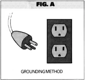
GROUNDING INSTRUCTIONS
This appliance must be grounded. If it should malfunction or break down, grounding provides a path of least resistance for electric current to reduce the risk of electric shock. This appliance is equipped with a cord having an equipment grounding conductor and grounding plug. The plug must be plugged into an appropriate outlet that is properly installed and grounded in accordance with all local codes and or dinances.
WARNINGImproper connection of the equipment-grounding conductor can result in a risk of electric shock. Check with a qualified electrician or service person if you are in doubt as to whether the outlet is properly grounded. Do not modify the plug provided with the appliance – if it will not fit the outlet, have a proper cutlet installed by a qualified electrician.
The Model CV950/CV950LE appliance is for use on a nominal 120 volt circuit and has a grounding plug that looks like the plug illustrated in FIG. A.
Make sure that the appliance is connected to an outlet having the same configuration as the plug. No adapter should be used with this appliance.
WARNING:ELECTRIC SHOCK COULD OCCUR IF USED ON WET SURFACES.
CAUTION:DO NOT USE ON WET RUG OR FLOOR.
![]()
CV950/CV950LE OPERATING INSTRUCTIONS

Inserting hose into valve (Fig. B). Lift lid on valve. Power unit will automatically come on. Insert hose into valve. Connect desired attachment and you are ready to vacuum.
Changing Bag (Fig. B). To keep your CV950/CV950LE at top efficiency, change the filter bag at regular intervals. Since cleaning schedules differ, check frequently in the beginning to determine proper interval. To maintain cleanability, replace filter bag when it is 2/3 to 3/4 full.
To Change the Filter Bag (Fig. B) – Locate canister, lift lid, and pull bag collar off connector. Open new bag, (expand pleats by gently pulling on bag), slide collar securely onto inlet connector. (See Fig.B.) Replace with Bag #7767. To reorder, check bag for instructions or contact:H-P Products, Inc.512 West Gorgas StreetLouisville, Ohio 44641-0912330-875-5556
To remove Secondary #4929 Filter & #4928/4934 Filter Supports for Cleaning (Fig. B). Take out bag 7767, pull Support 4934 off connector and out of canister. Take out 4929 & 4928. For reassembly, follow instructions in reverse order. NOTE: 4929 Filter wraps to front of 4928 Filter Support (Fig. B).
NOTE: This appliance has a THERMAL PROTECTOR built into the motor to prevent overheating. If motor will not operate, pull power cord plug out of receptacle -re-insert to reset.
If motor brushes or bearings are worn out, the thermal protector will trip off again after a short period of time. If this happens, service for this and any other servicing should be performed by an authorized service representative.
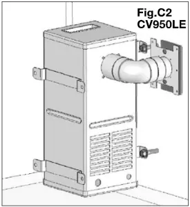
CV950/CV950LE INSTALLATION INSTRUCTIONS
WARNING: This unit must be installed in an accessible area with interior vent (Fig D).
The DIRT DEVIL® CV950/CV950LE can be installed in any one of four configurations. Figures C, D & E illustrate three configurations, with C being the most common. The one not shown is a variation of D.
1. Locate unit centrally so that area to be cleaned can be conveniently reached with standard 20′ or 30′ hose. Also locate near grounded electrical receptacle for easy plug-in connection of motor cord. Route supply cord so that it doesn’t rest against sharp edges or pinch points. See grounding instructions on page 3.
2. All dimensions below are approximate. To determine best configuration for your installation, temporarily install unit for best valve location. Be sure there is clearance to remove top cover and filter bag.
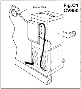
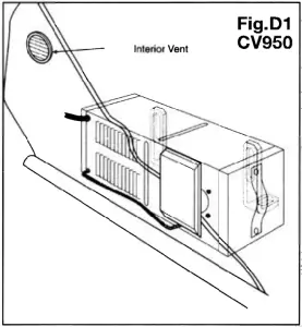
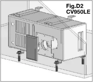
3. Determine valve location and cut 2 ¼” (58mm) wide x 3¾” (95mm) high opening, 9 7/8″(251mm) above the floor (Fig C) for upright canister position or 1¾” (45mm) above floor for horizontal canister position (see fig D).
Do not vent into a wall, ceiling or concealed space of a building or structure. Unit must be vented with interior vent or equivalent (see fig D).
5. Place the CV950/CV950LE canister in its approximate location before installing inlet valve (4940), mounting plate (4865), and inlet reducer (5531)(see fig.e).
6. Inlet valve switch should be wired at this point for convenience (See Figure E). Insert pre-stripped ends of 18-2 (1.00 mm -2) low voltage wire into holes on back ofinlet valve (4940), press in firmly and wires will lock automatically. Pull lightly to test for locking Connect other ends of wire from inlet valve to wire leads from relay (7090) with wire nuts provided.
7. Install inlet reducer (5531) to inlet connector (7464), glue if needed. Assemble inlet valve to wall with mounting plate (4865) using the four screws provided (see Figure E). Also, tabs on mounting plate should face away from inlet valve.
8. Secure unit to floor and or wall with mounting bracket(s) (7768) provided. Place square heads of mounting bolt in “C” channel of canister. Tighten nut to hold bracket(s) in desired location. Anchor leg of bracket to floor/wall with wood screws provided.
9. Plug in power cord from motor unit to nearby electrical receptacle Route power supply cord so that it doesn’t rest against sharp edges or pinch points. The CV950/CV950LE unit operates when the inlet valve lid is lifted.
VACPAN™ OPERATING INSTRUCTIONS
Simply switch on the VacPan automatic dustpan by pushing the raised tab with your foot. Switching on the VacPan activates your central vacuum. Brush dirt and debris toward the VacPan. When cleaning is complete, switch off the VacPan and the central vacuum system by pushing the raised tab with your foot.
VACPAN INSTALLATION INSTRUCTIONS
Part #7710
- VacPan requires a minimum 2-¼” toe kick height.
- Once the VacPan location is determined, cut 6-¾” long x 1 ¾” high slot in the cabinet toe kick to accept the VacPan.
- Run vacuum tube piping and low-voltage wire from the main piping line to the VacPan location.
- Access for final piping connections must be made. From below, cut an access hole underneath the cabinet, positioned so that final piping connections can be made through the access hole. Allow for ½” vertical play in vacuum tube piping at VacPan location so that final piping connections can be made.
- Attach low-voltage wire to the VacPan terminal connections marked low-voltage only.
- Prior to final installation, check for an airtight seal between the VacPan and elbow. Teflon tape may be used if required.
- Slide VacPan into mounting slot and secure to toe kick using the two #6 screws provided.
- Reach through access hole and make final piping connections.
VACPAN II OPERATING INSTRUCTIONS
Part #7981The VacPan II can be used as both an automatic dustpan and a standard hose inlet.
For automatic dustpan operation, slide top cover up, creating a sweep opening and automatically switching on central vacuum system. Sweep material to opening. When complete, slide top cover down, closing opening and automatically shutting off central vacuum system.
For standard hose inlet operation, ensure top cover is in fully lowered position. Grasp side finger grips in top cover and flip top cover up. The top cover will lock out of the way. Lift sprung flapper door open and insert central vacuum hose. Use your central vacuum hose as you would with any other standard inlet valve.
VACPAN II INSTALLATION INSTRUCTIONS
- VacPan II can be installed inside any wall with a minimum stud width of 2-¾”.
- VacPan II should be located against wall stud.
- Once the VacPan II location is determined and prior to applying the wallboard, attach Standard Mounting Bracket to the wall stud so that the center of the mounting plate is 4″ above the sub-floor.
- Attach VacPan II base stopper bracket, thereby allowing appropriate space for final installation.
- Run vacuum tube piping and low-voltage wire from the main line to VacPan II location and attach to mounting bracket.
- Allow other trades to complete construction including finished flooring and trim.
- Snap off two protruding tabs of VacPan II base stopper bracket and discard.
- Align VacPan II with mounting bracket. Height adjustment may be required depending on finished floor.
- For VacPan II height adjustment: The body can be shortened by scoring along Quick-Trim Grooves on back of body. The two piece front cover can be adjusted for height by twisting apart and engaging the mating teeth of the two parts. The VacPan II Entrance Ramp can be slid on mating body grooves.
- Attach low-voltage wires to VacPan II terminal connections.
- Slide VacPan II into mounting bracket and secure to wall using two 10 x 1-½” screws.
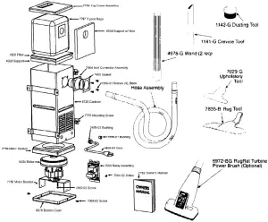
CV950 PARTS LIST
REPLACEMENT PARTS & PRICE LIST
| PART NO. | DESCRIPTION | RETAIL |
| 7767 | Paper Bag (3pk.) | 6.95 |
| 7757 | Canister w/plate | 46.54 |
| 7759 | Top Cover Assembly | 11.39 |
| 7768 | L-Mounting Bracket (x2) | 2.07 |
| 7760 | Motor Bracket | 4.94 |
| 7762 | Manual | N/C |
| 8404 | Motor/ Blower | 89.41 |
| 7758 | Motor Gasket | 9.36 |
| 7090 | Relay Assembly | 45.00 |
| 4934 | Filter Support w/hole | 1.97 |
| 4928 | Filter Support | 1.97 |
| 4929 | Filter | .75 |
| 2478-03 | Bushing (Power Cord) | .26 |
| 7599-01 | Bushing (24V) | .26 |
| 4926-04 | Power Cord | 4.92 |
| 7770 | Bolt (x2) | .21ea |
| 7771 | Washer- Nylon (x2) | .04ea |
| 7769 | Nut (x2) | .42ea |
| 7464 | Inlet Connector | 1.45 |
| 7455 | Inlet Gasket | .41 |
| 7655-01 | Screws – Black (x4) | .26 |
| 5531 | Inlet Reducer | .85 |
| 4941 | Inlet- Brown | 12.48 |
| 4940 | Inlet- Ivory | 12.48 |
| 4935 | Inlet – White | 12.48 |
| 4865 | Mounting Plate | 2.10 |
| 6678 | Bottom Cover | 10.24 |
| 7064-02 | Screws (x2) | .16 |
| 6972-BG | RugRat Turbine Power Brush (optional) | 51.75 |
| 7835-B | Rug Tool | 14.51 |
| 7029-G | Upholstery Tool | 2.69 |
| 1141-G | Crevice Tool | 2.15 |
| 1142-G | Dusting Tool | 3.80 |
| 4978-G | 1 Pc. Plastic Wand (2 req.) | 3.50 |
| 4962-03 | Screw | .16 |
| *Sub Assembly Part |
CV950LE PARTS LIST
NOTE: Inlet Valve Optional
REPLACEMENT PARTS & PRICE LIST
| PART # | DESCRIPTION | RETAIL |
| 7759 | Top Cover Assembly | 11.39 |
| 7767 | 3 Pack Bags | 6.95 |
| 4934 | Filter Support w/ Hole | 1.97 |
| 4929 | Filter | 0.75 |
| 4928 | Filter Support | 1.97 |
| 7464 | Inlet Connector Assembly | 1.45 |
| 7455 | Gasket | 0.41 |
| 7655-01 | Screws (x4) | 0.26 |
| 8728 | Canister | 46.54 |
| 7775 | Mounting Screw (x4) | 0.26 |
| 2478-03 | Bushing | 0.26 |
| 7599-01 | Bushing | 0.26 |
| 4926-04 | Cord | 4.92 |
| 7762 | Owner’s Manual | N/A |
| 7090 | Relay Assembly | 65.00 |
| 7064-02 | Screw | 0.16 |
| 4962-03 | Screw | 0.16 |
| 6678 | Bottom Cover | 10.24 |
| 7760 | Motor Bracket | 4.94 |
| 8404 | Motor | 89.41 |
| 7758 | Motor Gasket | 9.36 |
| 6972-BG | RugRat Turbine Power Brush (optional) | 51.75 |
| 7835-B | Rug Tool | 14.51 |
| 7029-G | Upholstery Tool | 2.69 |
| 1141-G | Crevice Tool | 2.15 |
| 1142-G | Dusting Tool | 3.80 |
| 4978-G | 1 Pc. Plastic Wand (2 req.) | 3.50 |
DIRT DEVIL® CV950 / CV9SOLEH-P PRODUCTS, INC.
LIMITED WARRANTY
Your DIRT DEVIL®, CV950/CV950LE which has been manufactured and inspected in accordance with carefully specified engineering requirements, is warranted to be free from defects in material and workman-ship for three years.
This warranty is, however, subject to the following qualifications, conditions and limitations which are set forth to provide you and all users of DIRT DEVIL® products with information concerning the duration extent, availability and applicability of this DIRT DEVIL® Limited Warranty, the procedure to be taken to obtain its performance and other information concerning the DIRT DEVIL® warranty policy.
DURATION OF WARRANTY AND TO WHOM EXTENDEDH-P Products, Inc. warrants to the customer, the DIRT DEVIL® equipment and accessories manufactured or supplied by H-P Products, Inc. to be free from defects in material and workmanship under normal intermittent use and when properly installed and operated, for a period of three years from the date of purchase by the first consumer purchaser.
EXCEPTIONS AND LIMITATIONS ON WARRANTYDefects, malfunctions, failure or damage caused by improper, unreasonable or negligent use or repair while the warranted parts are in the possession of the consumer are excluded from the warranty. The warranty does not cover unauthorized repair of the motor assembly.IMPLIED WARRANTY OF MERCH ANTABILITY OR FITNESS FOR A PARTICULAR PURPOSE ARE LIMITED TO A PERIOD OF THREE (3) YEARS FROM THE DATE OF PURCHASE BY THE ORIGINAL CONSUMER.
Some states do not allow limitations on how long an implied warranty Lasts, so the above limitation may be void where prohibited.
THIS WARRANTY IS EXPRESSLY IN LIEU OF ANY OTHER EXPRESS WARRANTIES AND DOES NOT COVER THE INSTALLATION OF EQUIPMENT. IN NO EVENT SHALL H-P PRODUCTS, INC, BE LIABLE FOR ANY OTHER OBLIGATIONS OR LIABILITIES, ESPECIALLY FOR ANY INCIDENTAL OR CONSEQUENTIAL DAMAGES TO ANYONE.
Some states do no allow the exclusion or limitation of incidential or consequential damages, so the above limitation or exclusion may be void where prohibited.
WE NEITHER ASSUME NOR AUTHORIZE ANY PERSON TO ASSUME FOR US ANY LIABILITY IN CONNECTION WITH THE SALE OR SERVICE OF THIS DIRT DEVILTM EQUIPMENT OTHER THAN HEREIN ABOVE PROVIDED.
PROCEDURE TO BE TAKEN TO OBTAIN PERFORMANCE OF WARRANTYTo secure repair of any warranted parts under this warranty, the following procedure should be taken:
The warranted parts, together with satisfactory evidence of the purchase date, must be delivered, with shipping and delivery charges prepaid, to one of the following: (1) the Distributor/Dealer from whom purchased; or (2) H-P Products, Inc., 512 West Gorgas Street, Louisville, Ohio 44641.
report this adUpon compliance with the above procedure H-P Products, Inc. will repair or replace, at its option, any warranted part which is defective. Such part or parts will be furnished without cost F.O.B. place of shipment. Return shipment will be made freight collect. All costs for service calls shall be borne by the one requesting service.
Dirt Devil® central vacuums are manufacturedunder exclusive license from Royal® Appliance Mfg. Co. by
H-P Products, Inc.512 West Gorgas StreetLouisville, OH 44641330-875-5556
[xyz-ips snippet=”download-snippet”]