dji AS-F1800 Aeroscope Stationary
Unit User Manual
Disclaimer and Warning
AEROSCOPETM is a comprehensive drone detection platform that rapidly identifies UAV communication links, gathering information such as flight status, paths, and other information in real-time (“Monitoring Data”). Monitoring Data stream helps users make an informed response as soon as possible. Please note that Monitoring Data does not involve personal data of DJI drone users. (Personal data is any information relating to an identified or identifiable natural person.) Unless pursuant to the requirement or request of any governmental or regulatory agency or court or tribunal of competent jurisdiction to the extent such disclosure is required by any valid laws, regulations, court orders or rules of relevant stock exchange, DJI will not disclose any personal data that DJI collect through DJI Products and Services to third parties.
As an AeroScope’s end user, you represent and warrant that (a) you are the eligible user of AeroScope. Examples of eligible users would be public safety organizations, law enforcement agencies, government agencies, regulatory bodies, and owners or operators of airports, power plants, and prisons; and (b) you will use AeroScope for monitoring public safety purpose only (“Purpose”); and (c) you will comply with any applicable laws concerning the use of AeroScope within the jurisdiction(s) of operation; and (d) you are solely responsible for the conducts of anyone that use AeroScope through your account (“Authorized User”), which may include your employees, consultants or contractors, or the employees, consultants or contractors of your affiliates, which are companies or entities that you own, that own you, or that have the same owner or corporate parent as you.
You acknowledge and agree that (a) DJI do not help you comply with any laws, rules, or regulations that may apply to your use of AeroScope, which is solely your responsibility; and (b) DJI shall not be liable for the authenticity of you; and (c) DJI will not be liable for any loss or damage you may cause; and (d) you will defend, indemnify, and hold harmless DJI, its affiliates, and its or their directors, officers, employees, agents, shareholders, successors and assigns from and against all claims, losses, damages, penalties, liability, and cost, including reasonable legal fees, of any kind or nature that are incurred in connection with or arising out of a third-party claim relating to, or arising from your breach of Purpose.
PLEASE NOTE THAT IF YOU DO NOT DISPUTE THIS DISCLAIMER IN WRITING BEFORE YOU USE AREOSCOPE, YOU ARE DEEMED TO HAVE ACCEPTED THE ENTIRE CONTENTS OF THIS DISCLAIMER AND ARE SOLELY RESPONSIBLE FOR THE CONSEQUENCES OF BREACH OF THIS DISCLAIMER.
Product Profile
Introduction
AeroScope detects UAVs flying within a particular surveillance area. Aeroscope receives UAV broadcast information of various formats, and then sends the information to the data processing platform via Ethernet or a 2G, 3G, or 4G wireless network card. The receiver and antenna can be configured in a number of different ways. Also, Aeroscope has integrated GPS, so users can see where the unit is on a map. And it[1] offers BIST (built-in selftesting) functionality for regularly timed self-tests and remote self-tests, as well as accurate environmental spectrum detection.
In the Box
Aeroscope Processor ×1Dongle[2] ×1Power Cable ×1Processor Mounting Bracket A ×2Processor Mounting Bracket B ×2Processor GND Cable ×1Pin ×5Female Power Connector ×1RJ45 Connector ×1RJ45 Waterproof Case ×1Screw Set ×1Screw M80 ×100 (4 pcs)Screw Nut M80 (4 pcs)Washer M80 (4 pcs)Screw M60 ×18 (4 pcs)
Only the waterproof dongle case is included in the North American version. The actual dongle must be purchased separately.
Overview
- Antenna Ports[3]Connected to the antennas with the antenna cables.
- Power PortConnected to a 220V AC power outlet.
- USB PortConnected to a wireless network card.
- Ethernet PortConnected to a computer.
- CAN Extension PortUsed for system debugging.
- UART Extension PortUsed for system debugging.
- IndicatorsSix LEDs that indicate the status of each module.
- GND ConnectorConnected to the metal bracket of the mounting device.
Indicators
LED1: Processor module status indicatorLED2: Network connection status indicatorLED3: UAV information capture indicatorLED4: Type 3 receiver status indicatorLED5: Type 2 receiver status indicatorLED6: Type 1 receiver status indicator
LED1: Processor module status indicator
It is used to indicate the processor’s working status.
LED2: Network connection status indicator
It is used to indicate the connection status between the processor and server.
LED3: UAV information capture indicator
When the Aeroscope receives UAV information, it can indicate the number of UAVs in the area.The UAV number is the reported number from the background. The same UAV serial number in a short time is regarded as one.
LED4: Type 3 receiver status indicator
LED5: Type 2 receiver status indicator
LED6: Type 1 receiver status indicator
Function Descriptions
Basic Functions
Features
Operation and Maintenance
Installation
Lightning Protection
The Aeroscope stationary unit system includes surge protection modules in the antenna module, power module, and Ethernet port. Aeroscope does not include a lightning induction system, and should be installed within the protected region of another lightning induction system. The protected region is calculated using the rolling sphere method.
The rolling sphere method assumes that an imaginary sphere of radius hr exists above the surface of a substation. The sphere rolls up and over (and is supported by) lightning masts, shield wires, substation fences, and other grounded metallic objects that can provide lightning shielding. A piece of equipment is said to be protected from a direct stroke if it remains fully within the surface of the sphere.
For a simple scenario in which there is only one lightning rod standing on a flat surface, the maximum distance that the Aeroscope can be placed from the lightning rod and remain within the protected region is calculated by the following equation:
Rx=√(h(2hr -h))-√(hx (2hr -hx ))
Where:
- rx is the maximum distance the Aerescope can be placed from the lightning rod.
- hx is the height of the protected object.
- h is the height of the lightning rod.
- hr is the rolling sphere radius. It depends on the lightning density and the protected matter and is given in the following table in the Chinese standard.
If Aeroscope is not under the protection of the nearest lightning rod, a designated lightning induction system should be designed by a qualified professional.
Finally, be sure to note the following:
- Ensure that rainwater cannot flow along the Antenna cable into the Aeroscope receiver.
- If the pole is made of metal, the frame and the pole should be separated using insulation.
- Indoor power outlets must have surge protection.
- Indoor Ethernet outlets must have surge protection.
Step-by-Step Installation Guide
For permanent setups, the Aeroscope unit can be mounted anywhere that meets all installation requirements, such as Lightning Protection, height restrictions, power connection, and network connection. The most common installation scenario is to attach it to a pole on the rooftop.
The standard procedure for pole-mounted scenarios is as follows:
- The pole should be firmly fixed to the ground (or other solid surface such as a rooftop). The diameter of the pole plus the insulation layer should be 120 mm to utilize the frames supplied with the stationary unit and antennas.
- Attach the stationary unit and the antennas to the pole. The processes for installing the stationary unit, G8 antennas, and G16 antennas are illustrated in below figures respectively.
Attaching the stationary unit to the pole
Attaching the G8 antennas to the pole
Attaching the G16 antennas to the pole
3. Connect the antennas to the unit via the antenna cable.a. If using G8 directional antennas, connect each antenna to one antenna port of the stationary unit with an antenna cable. Note that two adjacent antennas should be connected to ports at the top of the stationary unit, while the other two adjacent antennas should be connected to ports at the bottom. This ensures diversity gains will be realized. Below figure shows the connection configuration between the G8 antennas and the stationary unit.
Connection configuration between G8 antennas and the stationary unit
b. If using G16 high-gain antennas, the 2.4GHz antenna should be connected to a 5.8GHz antenna. Each 5.8GHz antenna has two antenna cable ports. The port marked “OUT” is for connecting to the Aeroscope unit, and the port marked “IN” is for connecting to the 2.4GHz antenna. Below figure shows the connection configuration and close-up view of a 2.4GHz antenna.
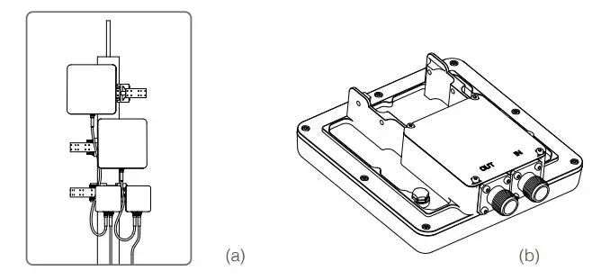
(a) The connections between the 2.4GHz antennas and the 5.8GHz antennas in G16 antennas installations. (b) The “IN” and “OUT” ports on a 5.8GHz G16 antenna.4. Often, the supplied power cable is too short for the connection between the stationary unit and the nearest available power outlet. In such cases, a qualified electrical engineer must extend the initial power cable to complete the connection.5. After powering on, check the LED indicators with reference to the Indicators section.6. Download DJI Assistant 2. from https://www.dji.com/aeroscope/info#downloads7. Install and run DJI Assistant 2 on a windowns computer (desktop or laptop).8. Connect the computer and the Aeroscope unit to the same router, or connect them directly via the Ethernet port.9. After the Aeroscope stationary unit is found on the DJI Assistant 2 start page, set the server IP and Port in Network Settings>Server Network Settings.10. Set the network mode to Wireless if using a wireless dongle. Set to Wired if using an Ethernet connection. Depending on network provider requirements, set the parameters manually or set the mode to Auto.11. Exit DJI Assistant 2.12. Restart the stationary unit.13. Connect the stationary unit to the interneta. It is recommended to always use Ethernet when possible, because the connection is stable and free of interference.b. If using a wireless connection, the dongle must be installed with an active SIM card. You may need to configure some parameters such as APN in DJI Assistant 2.14. Log into the Aeroscope web server https://Aeroscope.djiservice.org using your assigned account. The account management system in Aeroscope manages the relations between each account and each Aeroscope unit. Make sure the DJI admin has added your unit to your account. Otherwise, you will not see your unit when you log in.
Importing Certificates
In most cases, when you receive your Aeroscope stationary unit the certificate should already be imported. If the certificate doesn’t work or has expired, you will need to import a new certificate manually.
To import a new certificate, follow this procedure:
1. Acquire the certificate files from DJI. A single certificate consists of two files.2. Download DJI Assistant 2.3. Install and run DJI Assistant 2 on a windows computer (desktop or laptop).4. Connect the computer and the Aeroscope unit to the same router or connect them directly via the Ethernet port.5. After the stationary unit is found in Aeroscope, click it to enter the unit page. Under Advanced Functions, select the certificate. Import the certificate by selecting both files.
Power Cable Usage
Introduction
The Aeroscope Power Cable is used to connect the Aeroscope stationary unit to a power supply. You can connect it directly if it is long enough for your needs. Otherwise, you can extend it using the procedures provided below. In addition, the power cable can also be converted into a DC power cable if necessary.
In the Box
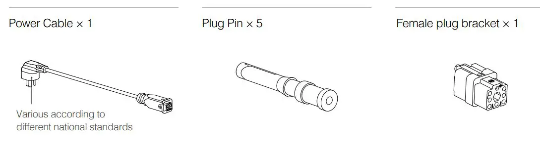
Modifying the Power Cable
You can use either of the first two procedures below to extend the power cable if it is not long enough for your needs. Additionally, you can use the third procedure to convert it into a DC power cable if necessary.
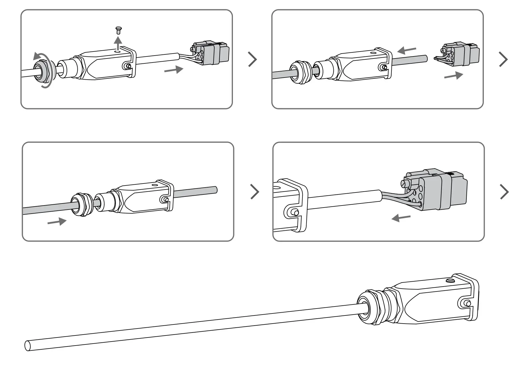
Procedure 1: Extending the AC Power Cable (New Plug Bracket)
- Loosen the nut that seals the cable in the waterproof module, and remove the screw on the top of the module to open it.
- Cut off the original female plug bracket. Remove the power cable and replace it with a longer one provided by yourself.
- Solder the provided plug pins onto the neutral and live wires of the new power cable (crimping pliers can also be used), then plug the two pins into the female plug bracket provided in the box.
- Remove the screw on the ground wire connector of the female plug bracket, then insert the ground wire of the power cable into the female plug bracket and retighten the screw.
- Insert the female plug bracket into the waterproof module and tighten the screw. Tighten the nut to ensure a good seal between the cable and waterproof module.
Procedure 2: Extending the AC Power Cable (Original Plug Bracket)
- Loosen the nut that seals the cable in the waterproof module, and remove the screw on the top of the module to open it.
- Cut off the original female plug bracket. Remove the power cable and replace it with a longer one provided by yourself.
- Solder the original female plug bracket onto the new power cable.
- Insert the female plug bracket into the waterproof module and tighten the screw. Tighten the nut to ensure a good seal between the cable and waterproof module.
Procedure 3: Converting to a DC Power Cable
Follow the procedure shown in the figure below to convert the power cable to a DC power cable. The modification procedure is the same as that of Procedure 1 for extending an AC power cable, but different pins are required. Connect the cable wires to the DC negative and DC positive poles on the female plug bracket to use the cable as a DC power cable.
After Modification
- Make sure the screw and washer on the waterproof module are securely tightened to fix the female plug bracket in place.
- After securing the female plug bracket in place, make sure to tighten the nut. The internal rubber on the nut should form a tight seal to ensure that the cable and plug are waterproof.
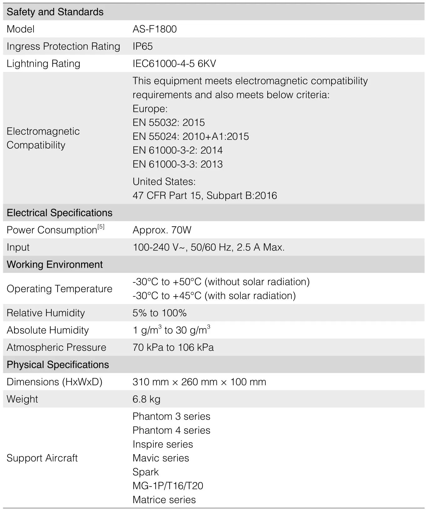
Specifications
Compliance Notice
NOTE: This equipment has been tested and found to comply with the limits for a Class A digital device, pursuant to part 15 of the FCC Rules. These limits are designed to provide reasonable protection against harmful interference when the equipment is operated in a commercial environment. This equipment generates, uses, and can radiate radio frequency energy and, if not installed and used in accordance with the instruction manual, may cause harmful interference to radio communications. Operation of this equipment in a residential area is likely to cause harmful interference in which case the user will be required to correct the interference at his own expense.
EU Compliance Statement: SZ DJI TECHNOLOGY CO., LTD. hereby declares that this device is in compliance with the essential requirements and other relevant provisions of the Directive 2014/53/EU. A copy of the EU Declaration of Conformity is available online at www.dji.com/euro-compliance EU contact address: DJI GmbH, Industriestrasse 12, 97618, Niederlauer, Germany
![]()
CAUTION: RISK OF EXPLOSION IF BATTERY IS REPLACED BY AN INCORRECT TYPE. DISPOSE OF USED BATTERIES ACCORDING TO THE INSTRUCTIONS
Equipment intended only for installation in a RESTRICTED ACCESS LOCATION.For PLUGGABLE EQUIPMENT, the socket-outlet shall be installed near the equipment and shall be easily accessible.
This content is subject to change.
Download the latest version fromhttps://www.dji.com/aeroscopeIf you have any questions about this document, pleasecontact DJI by sending a message to [email protected].Copyright © 2020 DJI All Rights Reserved.
Printed in China.
References
[xyz-ips snippet=”download-snippet”]