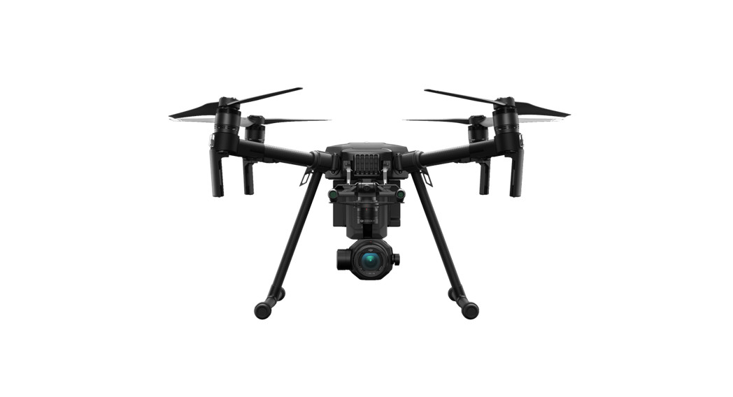
MATRICE 200 Series V2Maintenance Manualv1.02020.08
Searching for KeywordsSearch for keywords such as “battery” and “install” to find a topic. If you are using Adobe Acrobat Reader to read this document, press Ctrl+F on Windows or Command+F on Mac to begin a search.Navigating to a TopicView a complete list of topics in the table of contents. Click on a topic to navigate to that section.Printing this DocumentThis document supports high-resolution printing.
Introduction
This Maintenance Manual offers guidelines to help you in the daily upkeep and maintenance of your aircraft. A record table is also included to help you keep track of the maintenance records throughout the product lifecycle.This document will focus on the maintenance instructions and the notes, cautions, and warnings during use. Read the User Manual and Maintenance Manual carefully to optimize your user experience. If you have any questions on the maintenance operations, please contact DJI Support.
Disclaimer
Carefully read this entire document and all safe and lawful practices provided by DJI™ before using this product for the first time. Failure to read and follow instructions and warnings may result in serious injury to yourself or others, damage to your DJI product, or damage to other objects in the vicinity. By using this product, you hereby signify that you have read this disclaimer carefully and that you understand and agree to abide by all terms and conditions of this document and all relevant documents of this product. You agree to use this product only for purposes that are proper.You agree that you are solely responsible for your own conduct while using this product, and for any consequences thereof. DJI accepts no liability for damage, injury, or any legal responsibility incurred directly or indirectly from the use of this product.DJI is a trademark of SZ DJI TECHNOLOGY CO., LTD., and its affiliated companies. Names of products, brands, etc., appearing in this document are trademarks or registered trademarks of their respective owner companies. This product and document are copyrighted by DJI with all rights reserved. No part of this product or document shall be reproduced in any form without the prior written consent of or authorization from DJI.This disclaimer is available in various languages. In the event of divergence among different versions, the English version shall prevail. The final interpretation of this document and all related documents of this product belongs to DJI. This content is subject to change without prior notice. For up-to-date product information, visit http://www.dji.com and click on the product page for this product.
Safety Guidelines
Flight Condition RequirementsOperational RequirementsBefore use, read the Disclaimer and Safety Guidelines, User Manual, and Maintenance Manual carefully.Flight Restrictions
Please connect your aircraft to the internet to update the database of DJI GEO Zones regularly.Consult the relevant local government agencies or governing bodies before the flight to ensure you comply with all the relevant laws and regulations.
Storage and TransportationThere are safety requirements for the storage and transportation of Intelligent Flight Batteries.Please strictly follow these Intelligent Flight Battery Safety Guidelines.Firmware UpdatesTo optimize your experience, it is recommended to keep the firmware of the aircraft and remote controller up to date before each flight. Refer to the User Manual for instructions on running a firmware update.If the firmware update fails, restart the device and retry. If the problem persists, please contact DJI Support.Inspection and MaintenanceRoutine inspection before and after operations or regular maintenance can greatly improve the aircraft’s reliability, reduce potential safety hazards, and extend its service life.Routine InspectionMake sure to check the following before each flight.
Checklist When Powered Off
Type
Essentials
Structure
Visually inspect and use your fingers to feel the propellers, frame arms, arm junctions, and landing gears to check if they are in good condition. If there are any cracks or damage, replace the component immediately. If there are any foreign objects on the propellers, clear them before use.
The screws for all the connection structures are securely tightened, especially those for the arm junctions, landing gear junctions, and landing gear lockers.
The waterproof rear port cover (while the rear port is not in use), RTK rubber covers or upper shell rubber cover are in place.
The battery release button works normally.
Motors
The propellers are not visibly deformed, damaged, aged, or softened. If they are, replace the propellers immediately.
Rotate the motors manually to check if they are firmly installed without a gap between the motors and the motor base and the motors rotate smoothly without noise.
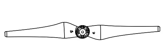
Propellers are mounted correctly. CCW propellers should be on motors 1 and 3, and CW propellers should be on motors 2 and 4. (The front-facing propeller on the right is motor 1, with motors 2, 3, and 4 arranged in counter-clockwise order.)
Refer to the propulsion system section in the Regular Maintenance Items.
Batteries
There is no foreign object in the battery ports on the aircraft and the ports are not misshapen.
The battery is secure to ensure that it does not come loose during flight.
The battery shell has no visible damage. If it does, DO NOT use the battery for flight.
Antennas
All the SDR, GPS/RTK antennas on the aircraft, and remote controller are tightened firmly and free of damage. They are in a place that will give the propellers proper clearance.
Gimbal (Payload)
The gimbal appears intact and can rotate smoothly in all three axes.
The lens is clean.
Other Payload (If applicable or available)
There is no blockage. The shell of the payload has no damage. The mounting bracket is secure and in good condition.
Remote Controller
The control sticks are centered in a neutral position, with no foreign object such as sand and soil, and can smoothly reach full ranges of motion in all channels.
The screen on the remote controller is clean and dry.
Damping Plate
The dampeners are not damaged. The damping plate has no crack or split. The gimbal connector is secure and cannot be rotated in the opposite direction after the gimbal is installed.
Infrared Sensing and Vision Systems
There is no blockage in the working range of the Infrared Sensing and Vision Systems and auxiliary lights, especially when using a non-DJI payload or accessory.
Check the lenses or glass of the Infrared Sensing and Vision Systems and auxiliary lights.a. Make sure there are no stickers or any other obstructions over the Infrared Sensing and Vision Systems.b. Clean the lenses and glass with a dust-free cloth if there is any moisture, fingerprint, or dirt.c. Contact DJI Support if there is any damage to the lenses of the Infrared Sensing and Vision Systems.
Emergency Supplies
Spare USB-C cables
Two pairs of spare landing gears
Two pairs each of spare CW and CCW propellers
Spare microSD cards
Screwdrivers, screws of all types used, cable ties, tape, a dry and soft cloth
A multimeter
A case to store emergency supplies
Checklist When Powered On
Remote Controller
Confirm the control stick mode (Mode 1/2/3), and check in the control stick calibration page in the app if the proportion of the control lever is correct.
The remote controller has sufficient power and the battery is firmly installed.
Confirm that the channel used is automatic or custom, and then choose the operation frequency and channel according to the signal to noise ratio.
Battery
All batteries, including Intelligent Flight Batteries and remote controller batteries, are fully charged.
It is recommended to charge and discharge the battery by following the standard instructions before the flight if the battery is stored for a period longer than one month.
The Intelligent Flight Batteries are firmly installed.
Check the battery level and voltage of each battery cell on the battery page in the app to make sure they are normal.
Flight Parameters Configuration
The Failsafe action of the aircraft is what fits your mission needs. For example, the aircraft will land as a failsafe within in 50 m of the Home Point, and it will hover as a failsafe when it is within 200 m from the Home Point.
The flight mode switch is set up correctly.
RTH altitude, height limits, distance limits, and obstacle sensing functions are set up correctly.
Module Auto-Check
View the module auto-check information on top of the screen in the app to check if there is an error prompt.
GNSS Positioning
There are at least 7 satellites and the aircraft works in P-mode.
Enable RTK function, select the correct base station and channel, and make sure that RTK positioning is in use. Check in the RTK page if the heading and positioning are fixed.
Sensors
Data on each IMU is shown in the app. IMU calibration can be performed successfully.
Data on each compass is shown in the app. The heading of the compass matches the physical one, and the needle is stable.
Compass calibration can be performed successfully.
The Vision System in all directions is enabled and there is no error prompt.
Top and Bottom Cooling Fans
Touch the shell of the cooling fans or listen carefully to check if the cooling fans work normally without noise.
Firmware Consistency
Connect the remote controller to the internet, then launch the app. Make sure that the app and the firmware versions of the aircraft, remote controller, payloads, and batteries match. Otherwise, the aircraft cannot take off or there may be risks.
Insert all Intelligent Flight Batteries into the aircraft to make sure that all of their firmware versions are up to date.
Motor Spin
Link the remote controller and aircraft, make sure the FPV camera display in the app works normally, and then perform Combination Stick Command (CSC) to start the motors in a safe indoor area to make the motors spin at an idle speed. Then test the following. NOTE: Stay away from the spinning motors and propellers to avoid injuries during the test.
The motors start without noise. There is no error prompt in the app.
At the beginning when the motors start or the end when the motors stop, observe the motors to make sure that motors 1 and 3 rotate counter-clockwise while motors 2 and 4 rotate clockwise.
Flight Test Checklist
Flight Test
Make sure that there are no potential safety hazards or people within 5 m of the aircraft.
Make sure that the satellite count is more than 10 and there is sufficient light. Start video recording.
In P-mode, perform CSC to make the motors spin at an idle speed on the ground. Push the control sticks in each direction lightly to test. Then push the throttle stick down to the bottom until the motors stop.
In P-mode, perform CSC to make the motors spin at an idle speed on the ground.Observe to check if the aircraft shakes. Then push the throttle stick down to the bottom until the motors stop.
In P-mode, take off and then hover at a height of 5 m for 1 min. Check to see the aircraft’s horizontal drift is no more than 1 m and the height drift is no more than 0.5 m. Check the shake of the aircraft, battery status, sound of the motors and propellers.
Push the control sticks in each direction lightly to check if the aircraft responds correctly.
Gradually increase the movement of the control sticks to observe the attitude response and the shake of the aircraft when braking.
Set height limits and distance limits. Then test if the aircraft can obey the limits.
In P-mode, enable obstacle sensing. Then test if the aircraft can avoid obstacles in front and upward directions.
In P-mode, fly the aircraft more than 20 m away from the Home Point at an altitude less than the preset RTH altitude. Initiate RTH using the RTH button on the remote controller to test if the aircraft can perform ascending, cruising, landing in order and the landing position has an error no more than 1 m from the Home Point.
Stop video recording after landing.
Once a high-value payload is used, perform the flight test without payload first, make sure that the aircraft is ready for use. And then out the payload to perform the flight test again.
Checklist after Landing
The propellers, motors, and aircraft bodies are intact, and there is no sign of collision or loose or broken structures.
The temperature of the motors is normal, with no signs of uneven heating.
Regular MaintenanceMake sure to perform inspection and maintenance regularly by following the standards below to keep the aircraft in a good condition and reduce safety risks.Regular Maintenance ItemsPropulsion System
Type
Inspection Process and Solutions
Illustrations
Motor Rotation
Unfold and secure the frame arms.
Rotate the rotor of the motor to check if there is any blockage or rubbing. Observe the gap between the rotor and stator of the motor to check if there is any rubbing with the motor base.
DO NOT fly the aircraft if there is any blockage or rubbing mentioned above. It is necessary to return to the factory for repair.
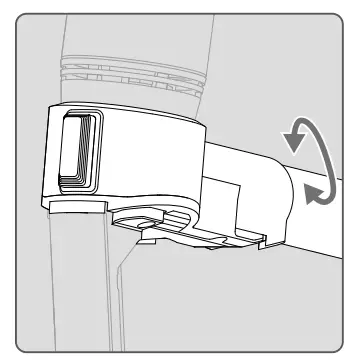
The connection between Motor and Arm
Check if the motor base is damaged, the motor and carbon tube connection is loose.
If there is any damage, return to the factory for repair.
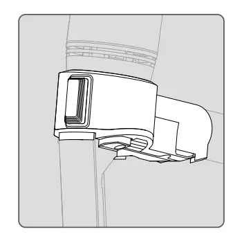
Motor Upper Cover
Ensure that the screws on the upper cover are not loose. There is no damage or crack on the quick-release propeller base.
If the quick-release propeller base is damaged or cracked, return to the factory for repair.
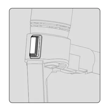
Motor Air Filters
Ensure that Air filters are not damaged.
If they are damaged, return to the factory for repair.
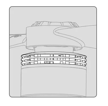
Propellers
Check the propellers for visible deformation, severe wear, nicks, and cracks, and if there are any foreign materials.
There are no foreign materials.
Clean the propellers with a dry soft cloth.
Replace the propellers immediately if visible deformation, severe wear, nicks, or cracks occur.
Flight Controller
After the aircraft is powered on and self-check is complete, there are no error prompts in the app related to the flight controller.
In outdoor open environments, the GPS signal has four bars within 1 min after powering on the aircraft, which indicates that the Home Point can be recorded automatically, and the RTK data meets the heading measurement standard.
In outdoor open environments, the interference of the compass after calibration is less than 50.
Sensor bias is less than 0.05 after IMU calibration.
Aircraft Structure
Type
Inspection Process and Solutions
Illustrations
Aircraft Appearance
The aircraft body is clean and not damaged.
Clean the aircraft body with a clean and soft cloth, especially for the lenses of the Infrared Sensing and Vision Systems and the heat dissipation vents.
Screws
All the screws on the aircraft body are tightened especially the screws connecting the motor and the carbon tube.
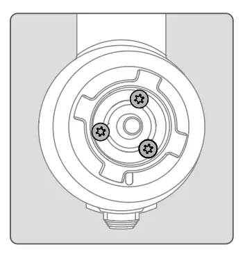
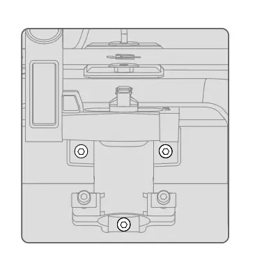
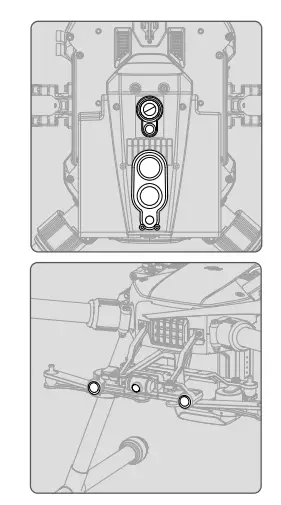
Landing Gear Base
Detach the landing gear to check the three screws as shown. There is no damage or crack around the screws.
If there is any screw loose, remove it to clear the remained glue on it, apply some LOCTITE 263 glue and attach it again.
Recommended torque: 40~60N. (a manual screwdriver is also suitable)
Inspection method: move the lock to see the screw is not loose, and that the landing gear can be disassembled and installed as per normal.
Follow the above steps to maintain and inspect the other Landing Gear Base.
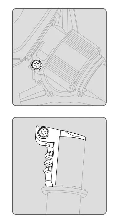
Frame Arms
Ensure the screw is secure, as shown in the illustration.
Ensure that the arm junctions are not damaged or cracked. If there is any damage or crack, return to the factory for repair.
The arm sleeves can be tightened in place.
Ensure that the carbon tube and the arm shaft connector are tightly attached together.
Frame Arm LEDs
There is no foreign object or damage on the surface.
Motor Base
The motor bases are not damaged or cracked.
The motor base and the carbon tube are to be attached firmly.
Battery Compartment
Ensure the battery port contractors are clean and dry without any corrosion. Also, there should be no trace of scorching.
Ensure that the battery release button functions normally, and the lock slider can move smoothly.
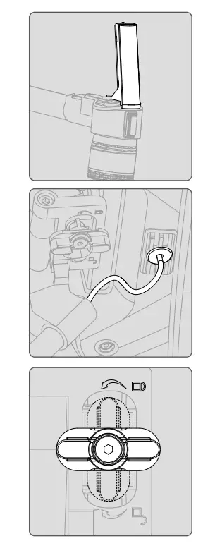
Antenna
Ensure that the RTK antenna knob screws are not loose.
The RTK antenna rubber plug and the wire must be tightly plugged and should not be damaged.
Ensure that the SDR antenna structure is not damaged or cracked, and there is no shaking.
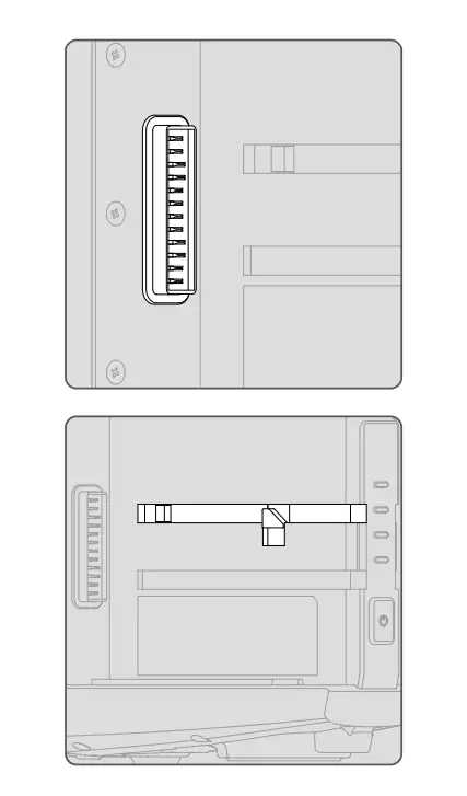
Data Ports
Ensure the expansion port cover can be closed and opened normally.
The expansion ports must be clean without any foreign matter or objects. The cable connector can be plugged and unplugged from the port smoothly.
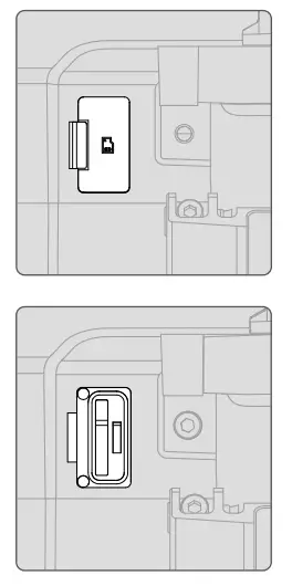
Ensure that the microSD card cover is not damaged or cracked, and can be closed normally.
Ensure that the microSD card can be plugged and unplugged from the port smoothly.
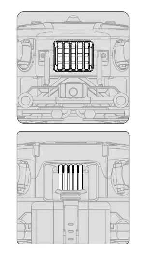
Heat Dissipation Vents
There is no blockage in the heat dissipation vents. The cooling fans work smoothly without noise.
Gimbal Damping Plate and Gimbal Damper
Ensure that the dampeners are not damaged, loose, or aged.
The gimbal connector should rotate smoothly. The surface must be clean without any foreign matter or dirt.
Ensure that the screws connecting the damping plate and aircraft body are secure.
Infrared Sensing, Vision System and FPV Lenses, Ultrasonic Module, and Beacons
Ensure that all lenses and ultrasonic module surfaces have no dirt or cracks.
Ensure that lenses are not loose and have no cracks.
Ensure that the upper and bottom beacons are not loose and cracked. Also, they should be located on the aircraft body properly.
Battery and ChargerBattery Maintenance ConditionsMaintenance is required when any of the events below occur.
Every 50 cycles.
The battery is idle for more than three months.
There is a maintenance prompt in the app.
Checklist for Maintenance
Charge and discharge the battery as per instructions.
Make sure the cell voltage difference is less than 0.1 V after the battery is fully charged and left stationary for six hours.
Make sure the battery is not swollen, leaky, or damaged.
Make sure battery terminals are clean.
Make sure the battery firmware is updated to the latest version.
Standard Charge and Discharge Operation Instructions
Charge the battery to 100% and leave the battery stationary for more than 24 hours.
Install the battery into the aircraft before flight. If the remaining power level is less than 20%, land the aircraft and remove the battery.
Leave the battery stationary for more than six hours.
Charge the battery to 100% power level.
Repeat the above steps.
Battery Replacement Standard
The battery is visibly swollen, leaky, or damaged.
There is a prompt of battery cell damage or over-discharge in the app.
The battery is rated for 200 cycles. It is not recommended to continue use afterward.
The battery error still exists after performing the standard charge and discharge operations twice
Battery Disposal
Fully fill in an insulated bucket with 5% salt solution. Put the battery into it for more than 48 hours to fully discharge the battery.
It is recommended to recycle the battery by a recycling agent to avoid environmental pollution.
Emergencies
Put out any battery fire using sand or a dry powder fire extinguisher.
Put the battery into a 5% salt solution immediately if the battery shell has visible damage. DO NOT use the battery afterward.
If any electrolytes make contact with your skin, immediately wash the affected area with clean running water or alkaline hand sanitizer for at least 15 minutes. See a doctor immediately.
Warnings
It is recommended to charge and discharge the battery in a special explosion-proof cabinet.
DO NOT charge the battery near flammable materials, objects, or on flammable surfaces.
DO NOT use the battery in a humid environment to avoid a shot circuit.
Never disassemble or pierce the battery in any way.
Store Intelligent Flight Batteries in a well-ventilated and dry place.
Initial RTH immediately when the battery temperature is 80° C (176° F) or higher.
Vision System Calibration
Vision System calibration is required when any of the events below occurs.
The total flight time is 200 hours.
There is a calibration prompt in the app.
Firmware UpdateMake sure that the firmware of the product and its relevant products are all up to date.After-Sales ServiceWarranty PolicyPlease visit https://www.dji.com/en/service/policy to check the product warranty period and warranty policy.Repair ChannelPlease visit https://repair.dji.com/repair/index and submit an Online Repair Request following the instructions.

 Searching for KeywordsSearch for keywords such as “battery” and “install” to find a topic. If you are using Adobe Acrobat Reader to read this document, press Ctrl+F on Windows or Command+F on Mac to begin a search.
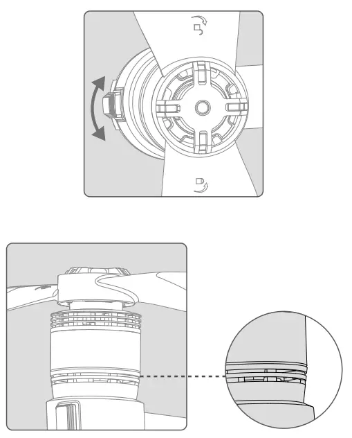


 report this ad